greenmark59 wrote:
I'm still in the planning stages and have decided to utilize a 1st gen Dodge Neon engine, manual tranny, front spindles (for the rear) and anything else that I can scavenge and use.
I have measured some dimensions of the Neon engine and how it mounts in the Neon and have come to the conclusion that I'm going to build a "book" chassis from the passenger compartment and forward. I will be looking to build an engine sub-frame that will attach to the front 2/3 of the chassis. The engine subframe should add only about 3-4 inches length to the standard book chassis's length so it shouldn't look too out-of-proportion from the norm.
I'm going to use a Fiero/Chevette front spindle since they have the same wheel bolt pattern and they are also decent spindles to work with. I'm going to start designing the front suspension using Staniforth's string computer method so that I can get the best setup I can before I start welding. In fact I'm going to build a 1/4 scale model of the whole thing using balsa wood and other miniature items to replicate my build.
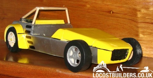
Because I won't have the engine in front, my tranny tunnel will not have to be really wide where the bellhousing usually comes out from the engine and I'll have more space for my feet and the pedals. Also I plan on using a "Catfish" nose from Kinetic Vehicles (see photo).
Just a tip for you. I built and used a Stnaforthish string computer and played with it and it was good for helping you visualize how things worked together etc. That being said, it isn't 1/100th as useful or practical as the "wishbone" program stickied in the suspension forum. It was much more useful since unlike a string computer it also shows lateral roll center movement. It allows you to introduce bump and roll as well and will give accurate diagrams and control arm lengths too.
The first step is to decide what wheel and tire size you are going to run and work from there. Bolt the Spindle to the wheel/tire combo with ball joints in place and then clamp everything into your intended static alignment on a hard level surface. You want 7 or so degrees of caster and a degree or so (depending on the car's prupose) of negative camber. Once you get it where you want it you need to carefully measure the height from the ball joint centers to the ground. (meaure it several times, it needs to be accurate) Next you need to set up a reference object to symbolize the midline of the chassis on the inside of the wheel/spindle/tire (I used a big carpenter's square) that is exactly 90 degrees to the ground. It also needs to be the distance of 1/2 of your track measurement from the center of the tire. Then you need to measure the distance horizontally from the vertical reference point (symbolizing the chassis midline) to the center of the balljoints. You now have the X and Y coordinates you need to allow you to play with the program and get meaningful results.
While everything is still clamped into place measure the steering arm joint center's location. You'll need that later to set up your steering system.
The other "chassis points" are wide open. Put them wherever you want ot achieve the roll center you want. I know this all may sound confusing and tedious, but it's really simple once you see the big picure. The hard part is accurately measuring the fixed points that you cannot change, which are the balljoint locations on the factory parts. Once you get these numbers nailed down you are off and running.
I've been at this since the fall and I'm getting comfortable with the program so if I can be of any help just ask. Good luck.