horizenjob wrote:
I replaced most of the round tubing in the midi version and did a little cleanup. It needs some more. When I grabbed your engine model somewhere I have lost track of the transmission. So I need that to see where the rear wheels go. I started to put in a rear bulkhead for the suspension. I also need to know where the motor mount and transaxle mounts go.
Briggs is also interested in doing a square tube version, so it's a common and sensible idea. I'd like these to be easy to build, they shouldn't be hard.
We need to think about the wheelbase. In this drawing I seem to have neglected to allow for steering of the front wheels.

Here's the Car9 Midi with your engine and converted to square tube with the start of some rear end tubing.
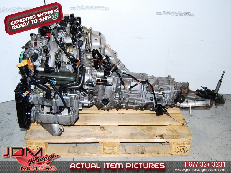
https://3dwarehouse.sketchup.com/model.html?id=ue9c6565a-3c1f-4725-acf9-26cb24e9d90aThe motor mounts are literally in line with the rear face of the motor that mounts to the transmission. I don't have extra mounts here to model but, the bottom left and right corners where the motor mounts to the transmission are close. Found this image on Google so you can see a visual of the angle they come out at.
You can see in the picture where the mount bracket butts up to where the transmission mounting face is and then in this picture below you can see the mount it's self offsets forward about 2-3 inches from there.

It may be easier to design the upper roll bars as well as the rear upper horizontal frame bar to be removable and just remove the motor/transmission from the top.
I added my basic transmission model started messing with the rear frame to work around the turbo and where the turbo downpipe should be. If I get anything significant I will upload it but, I get married tomorrow

so, probably won't have much time this week to mess with the model. I do want to create a more accurate transmission model though since the dimensions of mine are a slightly larger then actual (but the mount position is accurate). I uploaded the basic dimensions transmission, the lower square in the rear is where the mount is.
Basic Transmission
https://3dwarehouse.sketchup.com/model. ... caa1802439Briggs wrote:
Yeppers, brought home the rest of my tools today. Now gotta do some organizing in the garage. I would really like to start my build no later then November if at all possible.
Im working on a square tube version on Marcus' Car9 design with the roll cage bits and rear of the car in DOM tubing via scca roll cage specs. Im also using a R1 power plant with a prop shaft and a suby diff. My goal is to keep the car around 900 lbs if possible but deff under 1000 lbs.
I thought about doing a middy as well but, I wanting to use an R1 engine and not be chain driven. I decided on the FR setup, plus I'm a sucker for the original lotus and caterham look. Also helps that Tom is already done with his frame. If you haven't gone threw Tom's build thread you need too. Tom's skills are simply amazing and his attention to detail is mind boggling.
Marcus have you started on yours? I dont recall seeing any pics other then the one of the materials.
Great work on the engine BTW. Also, is the suby trans really that large? It looks way bigger then the engine in the model.
It's the square shape that makes it look a little larger then it actually is, and that I rounded up when making the model to give a little extra room. But, the engine mounting face is 15x15.5ish, the transmission is a good 26inches long, and that's not including the tailshaft section and the height from the bulge at the bottom where the front diff is to the top of the trans is 17inches.
The motor from crank pulley face to transmission mounting face is only 16.5 inches but, it's 32.5 inches wide.
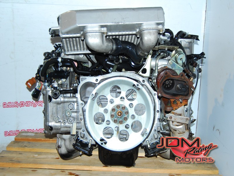
Here's another shot from google that shows the length.