LocostUSA.com

Learning how to build Lotus Seven replicas...together!
It is currently April 16, 2024, 4:44 am

All times are UTC - 5 hours [ DST ]


Post new topic Reply to topic  [ 23 posts ]  Go to page 1, 2  Next
Author Message
PostPosted: January 21, 2017, 10:47 pm 
Offline

Joined: March 10, 2006, 12:48 am
Posts: 294
Location: CT
Figured I should start a build thread sooner than later. :lurking:

Back story:
After building a few cars for the 24 Hours of LeMons, I decided I want to build a race car from the ground up. I started a 7 Series 2 clone with by dad circa 2005, but that project has stalled. Rather than pick up that chassis, I decided to start anew.

My goal is to build a reliable track and autocross car that can be driven to local events or for the occasional Sunday morning blat. I happened to get lucky and snag a wrecked Caterham SV chassis from a Lotus collector in MA, which I planned on reverse engineering, modifying around the Miata drivetrain and suspension. Came with rear fenders too! The chassis is available for free to anyone local who wants to do the same, or wants fun lawn art..

The frame is bent at every place there's blue tape.
Attachment:
DSC08291.jpg

Attachment:
DSC08287.jpg

Attachment:
DSC08295.jpg


Nosecone, scuttle and front fenders were sourced from Caterham. The chassis will be Caterham SV sized with some inspiration from the Caterham CSR.

Suspension will be '94 Miata knuckles with some modifications 8) . Custom control arms. I wrote a MATLAB script to help design the suspension (in another thread, can answer any questions on it if interested).


You do not have the required permissions to view the files attached to this post.


Last edited by Andy Bro on February 6, 2017, 11:20 pm, edited 3 times in total.

Top
 Profile  
Reply with quote  
 Post subject: Re: Andy's Brotus SV
PostPosted: January 21, 2017, 10:51 pm 
Offline
User avatar

Joined: August 2, 2009, 3:34 pm
Posts: 896
Location: Alberta
Nice find!

Good luck, have fun.

_________________
Trochu Motor League


Top
 Profile  
Reply with quote  
 Post subject: Re: Andy's Brotus SV
PostPosted: January 21, 2017, 10:58 pm 
Offline

Joined: March 10, 2006, 12:48 am
Posts: 294
Location: CT
Unfortunately, I don't have pictures from the early build stages anymore.

Chassis:
Started with a crashed 2001 Caterham SV. Between measuring it for days, building a CAD model, and stealing some measurements from John's SV build https://www.locostusa.com/forums/viewtopic.php?f=35&t=13510, I was able to build a model to start from. I then spent the next 6 months designing the suspension. With that close enough, sparks started flying!
Attachment:
20141203_183658.jpg


Rear suspension:
I'm a big fan of how well Caterham integrated the rear suspension on their CSR, and imitation is the highest form of flattery... Made some modifications to fit around the Miata differential.

I designed in some slight antiquat (~10% IIRC), so the jigging was a little tricky. You can see the fixture I used below. Had to stare at it the model for a while to figure out how to make it. Ended up modelling up the jig plates in Solidworks, to ensure they were the right distance apart (was too lazy to do the trig..), then cut some small shims to ensure the bushing sleeves weren't clamped perpendicular to jig plates. I turned some aluminum sleeves that fit inside the bushing sleeves and center onto the threaded rod.

Attachment:
20150328_152548.jpg

Attachment:
20150326_205936.jpg

Attachment:
20150118_201342.jpg

Attachment:
20150118_201329.jpg


You do not have the required permissions to view the files attached to this post.


Last edited by Andy Bro on January 21, 2017, 11:16 pm, edited 2 times in total.

Top
 Profile  
Reply with quote  
 Post subject: Re: Andy's Brotus SV
PostPosted: January 21, 2017, 11:09 pm 
Offline

Joined: March 10, 2006, 12:48 am
Posts: 294
Location: CT
More rear suspension:
Being that I plan on tracking the car, I wanted some robust control arm jigs that I can put aside until I need them after a hard cone hit or curb event. The side benefit of using a metal jig is that grounding is easy. I've been TIG'ing most everything up to now. Sure, it's slow, but this is about learning new skills after all, right?

I'll upload a picture of the control arm jigs tomorrow. Can't find any pics now. :BH:
Attachment:
20150527_115446.jpg


The control arms aren't quite done yet. I need to box the ends still.
Inspiration: Image

I chose to mount the bushings on the chassis side and brackets on the control arms due to packaging. I felt that the bushing sleeve integrated into the round tube rear chassis better than I could pull off with the rectangular brackets. Plus, it looks pretty neat. :lol:
Attachment:
IMG_20160530_152407878.jpg


Forgot to include some fun stuff. I modified the rear uprights to eliminate the bushings at the upright end. I will use 1/2-20 rod ends at the lower control arm, and I converted the upper bushing to a 1/2" spherical bearing. The LCA modification was simple. I drilled and reamed the upright holes to 5/8" and used a piece of 5/8" OD, 1/16" wall tube to act as a compression sleeve. That got knocked in and welded. I followed suit from another post on the forum for the upper. I reamed out the bushing bore in the upright to the next imperial size, then welded a sleeve into the upright the spherical bearing sleeve into that. I stole the idea from here:
Image
We'll see how well the upper bearing lasts.
Attachment:
20160226_174304_LLS.jpg


You do not have the required permissions to view the files attached to this post.


Top
 Profile  
Reply with quote  
 Post subject: Re: Andy's Brotus 7
PostPosted: January 22, 2017, 7:04 pm 
Offline

Joined: March 10, 2006, 12:48 am
Posts: 294
Location: CT
More catching up.

Wall of control arm jigs. The big one one the right is for all the rear control arms. Symmetry is most helpful. Left two jigs are for the front. The upper control arm is the same on left and right side, but the lower is unique per side.

Attachment:
IMG_20170122_171030110.jpg

Attachment:
20160131_175436.jpg

Attachment:
IMG_20160626_191231618.jpg


I opted not to use the standard Miata lower ball joint. Instead, I'm using a beefy monoball pin and high misalignment spherical bearing. I got the pins and bearings from UB Machine. Also got a pair of the weld cups from them too, but I butchered them up and had to make replacements (picked up a lathe between when I initially bought them and when I screwed 'em up :BH: )
http://www.ubmachine.com/balljointspins.html

Attachment:
20150616_190816.jpg


Craftsman 12-36 lathe has come in pretty handy. If only I was better with it.
Attachment:
20150413_073444.jpg

Attachment:
20150616_190738.jpg


The upper balljoint is the standard Mazda B2200 tie rod end. Don't have any great pictures. Also took the tried and true approach for the tie rod ends. Heated and twisted the knuckle, then reamed the taper from the other side. I might weld some material to the old taper and then re-ream to get full contact on the tierod end taper.

-Andy


You do not have the required permissions to view the files attached to this post.


Top
 Profile  
Reply with quote  
 Post subject: Re: Andy's Brotus 7
PostPosted: January 22, 2017, 8:09 pm 
Offline

Joined: March 10, 2006, 12:48 am
Posts: 294
Location: CT
Sorry for the odd order of my posts. I'm trying to post up in the order I built it and can go into more detail in there's anything yall are interested in.

More front suspension! :cheers:

The Caterham SV is a few inches wider than their base 7. Conveniently, the stock Miata steering rack width is almost perfect. That said, I designed the steering rack mounts to slide forward/aft, and can shim up as needed. Analytically, bump steer is damned near zero. At the tack welded stage, it was pretty good, but it was hard to get repeatable measurements. As such, the steering rack mounts will get finish welded once I get it back on the ground again.
Attachment:
20160130_145517.jpg

Attachment:
20160402_163439.jpg

Attachment:
20151230_132523.jpg


Now: Shocks.
I have a habit, in case you haven't noticed by now, of making things more difficult for myself. I obsessed on what shocks to get. I've always been a fan of Bilstein, but their adjustable units re just too far outside of my price range. I also wanted to use pushrods/rockers in the front. Problem was: I don't have alot of room between the shock/spring and the steering rack on the driver's side.

I narrowed my search down to small shockbody shocks. I don't remember all of the options that I investigated, but I do remember looking at some AFCO midget coil-overs, and maybe QA1s. In the end, I chose the Bilstein SG line. The damping isn't adjustable, but you can get a variety of valving options off shelf at $90 ea, and they should hold up well. I talked with Bilstein's tech support and got the dyno for the front shocks (SG7-4020 IIRC). I need to measure the final rear motion ratio, calculate the needed spring rate, then I'll be on the phone with tech support again.
Attachment:
20160217_183534.jpg

Attachment:
20160409_121458.jpg


I'm using a set of welded rockers for now. They pivot on oil impregnated, flanged bushings. If they don't hold up well, I'll upgrade to needle bearings and thrust washers, and probably go with shiny aluminum rocker... because racecar.


You do not have the required permissions to view the files attached to this post.


Top
 Profile  
Reply with quote  
PostPosted: February 6, 2017, 11:29 pm 
Offline

Joined: March 10, 2006, 12:48 am
Posts: 294
Location: CT
Rolling the chassis outside felt like the logical next step. The front suspension could have held up its weight if I had springs, but the rear suspension mounts weren't stiff enough (and the shock mounts also aren't in yet).
Attachment:
IMG_20160702_142839531_2.jpg

Attachment:
IMG_20160702_142706445.jpg


In addition to the motivational boost garnered from seeing the chassis in daylight, I wanted to ensure the curved tube next to the human cargo is visually concentric with the rear fender and tire. It sure was a nice day in July when my wife and I were iterating, on the best location, and this is what we came up with:
Attachment:
IMG_20160702_150428991.jpg

Attachment:
IMG_20160704_154610462.jpg


In hindsight, I probably should have braced the rear subframe better before taking it off the jig.... To ensure I don't screw anything else up if I have any future moments of weakness and need to see the car outside, I decided to shore up the rear end a little.
Attachment:
IMG_20160713_175104379.jpg

Attachment:
IMG_20160713_175119119.jpg


Next installment: motor and transmission mounts :cheers:

-Andy


You do not have the required permissions to view the files attached to this post.


Top
 Profile  
Reply with quote  
PostPosted: February 6, 2017, 11:57 pm 
Offline

Joined: March 10, 2006, 12:48 am
Posts: 294
Location: CT
Motor mounts:
I used the same mounts that Caterham used, which are of course from British parts big pieces. ÜRO PARTS: C18556 from '61-71 Jaguar XKE.... a whooping $5.50 from RockAuto. Feeling generous, I splurged and picked up 4.

Design:
Again, I'm pulling design cues from Caterham and some members on the board here. I started with 2"x3"x.083" square and cut it diagonally such that I have 2x 2" wedges, tapering from about 2.5" to .5" over 10" length. I wish I took pictures of the process...

The arms are welded to .250" plate, bolted to the block in 4x places. I tried the use as much of the plate footprint as I could for the arm so as to minimize the bending load on the plate. I'll snap a picture of the Caterham mount I used as inspriation and you'll see where it bent. At the outboard end, I'm using .875" OD, .5" ID tube as the sleeve for the 1/2-20" motor mount bolt.

The open face of the arm got welded closed with 2"x.083" strip.
Attachment:
IMG_20160615_184811144.jpg

Attachment:
IMG_20160618_170959911.jpg


On the chassis side, I'm using .75" OD, .375" ID tube as a sleeve. I'm planning on using washers under the bolt head (bolt feeds up from the bottom) to held distribute the load.

Transmission mount:
Stole this idea from a member on the forum here. It's pretty simple - I had some 1" aluminum plate lying around, so I used that to make the adapter. The only tricky part due to the nose down position of the engine (I matched the driveshaft angles) to help the engine sneak under the hood line, I needed to drill the holes on an angle so the trans mount isn't always loaded in bending.
Attachment:
IMG_20170122_171115787.jpg


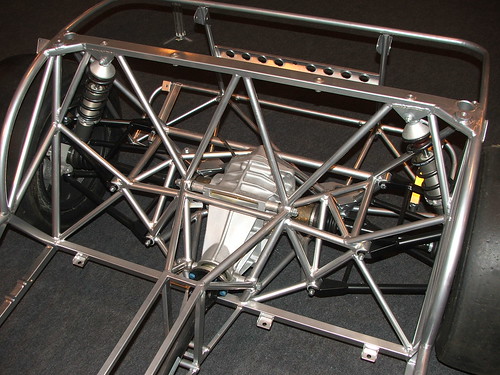
With the drivetrain mounted, I spent a week triangulating the outer portion of the chassis and building the rough transmission tunnel.
Attachment:
IMG_20160705_194536252.jpg

Attachment:
IMG_20160704_180524493.jpg


Next installment: FIELD TRIP to England :cheers:
-Andy


You do not have the required permissions to view the files attached to this post.


Top
 Profile  
Reply with quote  
PostPosted: February 7, 2017, 12:12 am 
Offline

Joined: March 10, 2006, 12:48 am
Posts: 294
Location: CT
I was lucky enough to get paid to go to the UK for work, and happened to squeeze in a stop at the Caterham factory on my way out. I probably spent an hour walking around their showroom, taking pictures, drooling, taking pictures....

If I end up there again with more time, I will be hard pressed to not rent a real 7.
Attachment:
IMG_20160806_103124361.jpg

Attachment:
IMG_20160806_103724745_HDR.jpg


Wish my garage was this clean:
Attachment:
IMG_20160806_103457341.jpg

Attachment:
IMG_20160806_104916852.jpg


Also should bring a bigger suit case:
Attachment:
IMG_20160806_105054267.jpg


Nifty diffuser - I wonder how effective it is:
Attachment:
IMG_20160806_105446101_HDR.jpg


Caterham F1 car kit:
Attachment:
IMG_20160806_104042662.jpg


Lotus F1 car @ Picadilly
Attachment:
IMG_20160805_154813285.jpg


Next up:
Small stuff that held me up.
Front mount for differential
Steering shaft
Pedals
Seat & Sliders

-Andy
:cheers:


You do not have the required permissions to view the files attached to this post.


Top
 Profile  
Reply with quote  
PostPosted: February 7, 2017, 2:51 am 
Offline
User avatar

Joined: December 4, 2011, 6:19 pm
Posts: 830
Andy,

Nice build! And thanks for the pictures from England, I really enjoyed them.

That Caterham chassis was bent in a whole lot of places. Do you know what the story was? What happened to it to damage it that badly?

Bill

_________________
Bill H
Winnipeg, MB, Canada


Top
 Profile  
Reply with quote  
PostPosted: February 7, 2017, 11:12 am 
Offline

Joined: March 10, 2006, 12:48 am
Posts: 294
Location: CT
BHRmotorsport wrote:
Andy,

Nice build! And thanks for the pictures from England, I really enjoyed them.

That Caterham chassis was bent in a whole lot of places. Do you know what the story was? What happened to it to damage it that badly?

Bill


I'm the third owner of the frame since its demise, so some of the details have been lost. The previous owner said a Jeep clipped the car at an intersection. It hit the driver's side near the pedal box. The curved tube behind the driver is a little flattened and you can clearly see the dented pedal mounts. It's interesting how the steering rack got pulled outwards and the LCA front mount ripped off, but the USA mounts look solid. It's also curious how the rest of the chassis bent, but I don't know if there were any secondary impacts.


Top
 Profile  
Reply with quote  
PostPosted: March 24, 2017, 9:53 pm 
Offline

Joined: March 10, 2006, 12:48 am
Posts: 294
Location: CT
It's Friday night, let's talk about shafts.... steering shafts. I spent far too long looking for an alternative before I decided to just hack into what I have. In the end, this was far cheaper.

I'm using the standard Miata column, but I didn't like how beefy the stock column is. Luckily with a little creative dissection, the 8lb steering column becomes a 2 lb column! :cheers:

Attachment:
IMG_20160822_190446805_2.jpg


I turned a bearing cup for the upper bearing which will mount right into the frame. I plan on replacing the open NSK bearing with a double shielded bearing to protect it from the elements. On the lathe, I cut off the steering wheel splines and the pilot fit for my quick release (a nice Go-Race unit http://www.demon-tweeks.co.uk/motorsport/steering-wheel-bosses-accessories/go-race-self-aligning-formula-quick-release-steering-boss-weld-on from the UK, post Brexit vote with a favorable exchange rate).

At the other end, as many of us experience, the shaft just wasn't long enough, but the welder can fix this one. With some cutting, turning, welding the shaft is extended past the bottom of the pedal box, where it's supported by a standard firewall steering shaft bearing.
Attachment:
IMG_20160909_160929295.jpg

Similarly, the lower shaft needs to be extended as well. Please pay no attention to the poor surface finish.
Attachment:
IMG_20170324_205716141.jpg

Attachment:
IMG_20170324_205720820.jpg


And the steering wheel now has a home!
Attachment:
IMG_20161030_190505199.jpg


You do not have the required permissions to view the files attached to this post.


Top
 Profile  
Reply with quote  
PostPosted: March 24, 2017, 10:21 pm 
Offline

Joined: March 10, 2006, 12:48 am
Posts: 294
Location: CT
I'm going to skip some boring steps that I'll update later. The parking brake was tedious :BH:

But, this was much more fun.
WRX: Good!
Stainless L bends. My first time backpurging.
Attachment:
IMG_20160606_171503263.jpg

Attachment:
IMG_20161122_103624022.jpg

Attachment:
IMG_20170102_123555798.jpg

Attachment:
IMG_20170102_162441423.jpg

Attachment:
IMG_20170107_173438784_HDR.jpg

Attachment:
IMG_20170301_153445463.jpg

Attachment:
IMG_20170302_131116961.jpg

Attachment:
IMG_20170302_131158868.jpg


You do not have the required permissions to view the files attached to this post.


Top
 Profile  
Reply with quote  
PostPosted: March 25, 2017, 11:54 am 
Offline
User avatar

Joined: February 9, 2016, 8:46 am
Posts: 392
Location: New Jersey
Wow, Schedule 10 on those elbows! :shock: Those ain't ever going to fail! :wink:

_________________
Dismantalus, Fabricatus, Assemblus.....
Certified Welder, Certified Welding Inspector, Full Time Car Freak...In New Jersey no less!


Top
 Profile  
Reply with quote  
PostPosted: March 25, 2017, 4:42 pm 
Offline
User avatar

Joined: August 29, 2010, 11:43 pm
Posts: 225
Location: East st Paul, Mb
Andy Bro wrote:
WRX: Good!


HAHA! Yup, WRX good! Nice looking manifold.

_________________
Chris


Build log http://www.locostusa.com/forums/viewtopic.php?f=35&t=12374
Completed build showcase http://locostusa.com/forums/viewtopic.php?f=33&t=16865


Last edited by cboettch on April 16, 2017, 9:44 pm, edited 2 times in total.

Top
 Profile  
Reply with quote  
Display posts from previous:  Sort by  
Post new topic Reply to topic  [ 23 posts ]  Go to page 1, 2  Next

All times are UTC - 5 hours [ DST ]


Who is online

Users browsing this forum: No registered users and 12 guests


You cannot post new topics in this forum
You cannot reply to topics in this forum
You cannot edit your posts in this forum
You cannot delete your posts in this forum
You cannot post attachments in this forum

Jump to:  
POWERED_BY