LocostUSA.com

Learning how to build Lotus Seven replicas...together!
It is currently April 26, 2024, 6:06 am

All times are UTC - 5 hours [ DST ]


Post new topic Reply to topic  [ 39 posts ]  Go to page Previous  1, 2, 3  Next
Author Message
PostPosted: May 8, 2019, 10:53 am 
Offline

Joined: September 19, 2009, 12:33 pm
Posts: 498
Lonnie-S wrote:
If you're going with an IRS, I can't be of much help as I have a live, 7.5" Mustang rear axle from a 1994. I can't tell you which IRS rear axles will work best. Is that the question you want answered?


He's asking how much space he needs between the inside face of the wheel/tire and the frame.

https://trackmustangsonline.com/threads ... nce.13708/

5mm is enough, 10mm is plenty. You'll want to check the arc of your suspension travel and see how much the wheel moves in and out.

MacGyver wrote:
I beleive Rod's build used a couple drivers side explorer axles, but I can't find the lengths listed on them.


It's not clear if you're talking solid rear or IRS. Rod used a solid rear axle.

Per RockAuto, the Explorer axles are:

Right: 27-13/16" long
Left: 30 11/16" long

Quote:
When my frame is 46" wide, and the wheel mounting surfaces are coming out to around 63-1/2" it seems to me that I'm going to need nearly 3.5" of offset in my wheels to get them within 1-1.5" of the frame. Am I missing something, or (sorry to be lazy) can someone just tell me what axles to look for that will work with my 31 spline rear end? I'm looking to use 17x9 rims in the rear.


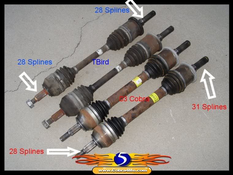
The Explorer rear end has an offset pumpkin. You can cut the long side to make it the same width as the short side and use a short side axle. Then your WMS-to-WMS measurement is 56.5". Stock Thunderbird IRS WMS wider than that.

TRX, I understand the mustang has been used plenty, but the one I was specifically mentioning was a 2015-18 rear setup. I'm not comfortable walking up to a strangers car and crawling under it. [/quote]

Search car-part.com for 2015 Ford Mustang Rear Suspension, then choose "Complete Assembly." Every 2015-up Mustang has a limited slip, the engine, trans, and PP will just dictate gear ratio.

Image

Any vendors selling Mustang upgrades would be a good place to see pictures of suspension components.

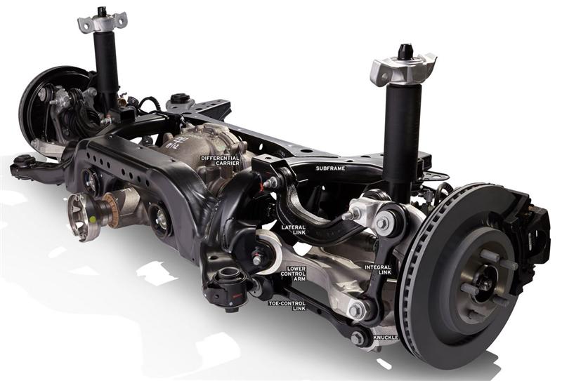
Here are some good pics of the IRS assembly:
https://thefactoryfiveforum.com/showthr ... -it-begins

You can find them under $600 for an 8.8 LSD, IRS, disc brakes, and axles that can hold 500+hp on a 3800lb car. Overkill and too wide for a basic Locost but surely an awesome option for a vintage retrofit.

_________________
Ford 5.0 into an M3
mikaelvroom.com | @MikaelVroom


Top
 Profile  
Reply with quote  
PostPosted: May 8, 2019, 11:02 am 
Offline

Joined: September 19, 2009, 12:33 pm
Posts: 498
MacGyver wrote:
Or if someone knows what half shafts will work for my situation, please advise. (2008 ford explorer 31 spline rear carrier, 9" wide wheels, markviii uprights and spindles)


You'll want Cobra axles - 31 spline inner, 28 spline outer. Are you keeping the Mark VIII bolt pattern or converting to the more common Mustang bolt pattern?

Image

_________________
Ford 5.0 into an M3
mikaelvroom.com | @MikaelVroom


Top
 Profile  
Reply with quote  
PostPosted: May 8, 2019, 3:46 pm 
Offline

Joined: March 4, 2019, 3:49 pm
Posts: 12
Laminar, that mustang irs picture is exactly why I decided not to go with that setup - the integral, lateral and toe-control links scared me enough to steer clear but man was it tempting. I could have had one delivered to my shop for $450 with a 3.15 ratio and everything would've worked together right off the skid. I'm sure I'll be way over that in mix-and-match parts and time wasted making things work together.

Typo on my part referring to Rod's post and an IRS build. I meant Phil's LS build.

I have the ability to re-drill the mark8 hubs and make a hub-centric spacer at my shop so I'll do that if for no other reason than to give me lots of options.

I'll keep an eye out for cobra axles, but they seem to command a premium. You mentioned cutting down an explorer axle, I'm under the impression doing so required welding which would ruin the temper on the axle, but please correct me if I'm wrong. Cutting a shaft and welding to maintain concentricity would be relatively easy for me.

Thanks for the info, lots to work with.


Top
 Profile  
Reply with quote  
PostPosted: May 9, 2019, 9:46 am 
Offline

Joined: September 19, 2009, 12:33 pm
Posts: 498
MacGyver wrote:
You mentioned cutting down an explorer axle, I'm under the impression doing so required welding which would ruin the temper on the axle, but please correct me if I'm wrong. Cutting a shaft and welding to maintain concentricity would be relatively easy for me.


When I mentioned Explorer I was still talking about the solid rear end. RockAuto tells me the IRS Explorer axles were 31-spline inner and 29-spline outer, so they wouldn't work with your Mark hubs directly, but perhaps some adaptation of CV joints would make the connection possible. Explorer parts are great because Ford made a billion of them so axles are only $50 each.

Several members here have cut axles, rewelded, and sleeved them with success:
http://www.locostusa.com/forums/viewtop ... 5&start=30

Certainly it depends on your method and expected level of abuse.

_________________
Ford 5.0 into an M3
mikaelvroom.com | @MikaelVroom


Top
 Profile  
Reply with quote  
PostPosted: May 9, 2019, 10:50 am 
Offline
User avatar

Joined: October 24, 2008, 2:13 pm
Posts: 5326
Location: Carlsbad, California, USA
It looks like you got your answers plus some.

The one you directed at me just has to do with subscribing to a topic and getting e-mail notices when something new is posted. That's why I responded so quickly. I just happened to be online when the notice arrived.

Cheers,

_________________
Damn! That front slip angle is way too large and the Ackerman is just a muddle.

Build Log: viewtopic.php?f=35&t=5886


Top
 Profile  
Reply with quote  
PostPosted: June 13, 2019, 1:52 pm 
Offline

Joined: March 4, 2019, 3:49 pm
Posts: 12
I've made some progress on the car, but mostly in the design or purchased parts phase. I think I've got my rear suspension design worked out - anyone see any major issues?

Attachment:
RearIRS.1.JPG


Attachment:
RearIRS.2.JPG


I'm pricing out the DOM for the round bits and am finding prices around $5/foot almost regardless of size (1"-1.75") - does this seem right? If so, it's going to be near $700 just for the DOM (I have to buy full lengths). I do have access to some 1" x .065 stainless DOM I can get for free, but has anyone used ERW or steel (not iron) pipe for some of the pieces? I know it's not as strong, and pipe has been known to fail in some bad ways, but are my components being subjected to forces that would break a short piece of pipe? If so, maybe I need to rethink my safety factor in the design.


You do not have the required permissions to view the files attached to this post.


Top
 Profile  
Reply with quote  
PostPosted: June 13, 2019, 7:59 pm 
Offline
User avatar

Joined: January 2, 2009, 1:45 pm
Posts: 1322
Location: Halifax, Nova Scotia
Unless something is missing, shouldn't the upper link be an A-arm or have a trailing link associated with it?

_________________
Warren
Isuzu Pickup/SR20DE, +401 COLD frame
Build Log: viewtopic.php?f=35&t=11601


Top
 Profile  
Reply with quote  
PostPosted: June 14, 2019, 7:26 am 
Offline

Joined: March 4, 2019, 3:49 pm
Posts: 12
Based on what I've seen, the design I've got will give me camber adjustment/resistance with the upper link, and the lower will provide toe adjustment with the rod ends and take the forces that would contribute to toe in/out. Unless I'm missing something, Factory five handles the IRS on the MarkIV this way as well. A lot of the designs I've seen with the upper A's seem over constrained and unnecessary to me, and turning one rod end for adjustment would require turning at least two others to prevent a binding force while the suspension is working.

With that being said, if there's something I'm missing, please feel free to educate me, or point me in the direction to be educated. I'm really just copying bits of other peoples designs that make the most sense to me.

Since my recent questions about erw, I found some really informational pages about the differences (or lack there of) between ERW and DOM. As I mentioned, I'll still use DOM for the roll cage, but do plan on using ERW on the diagonals, and probably the suspension arms as well.


Top
 Profile  
Reply with quote  
PostPosted: June 14, 2019, 7:38 am 
Offline
We are Slotus!
User avatar

Joined: October 6, 2009, 9:29 am
Posts: 7651
Location: Tallahassee, FL (The Center of the Known Universe)
Warren Nethercote wrote:
Unless something is missing, shouldn't the upper link be an A-arm or have a trailing link associated with it?
I'll second that motion! My first version of the UCA with my T-bird uprights used the single-tube design you show. After I put a GoPro on the suspension and noted the upper moving fore-and-aft under cornering and braking loads, I re-made the uppers to be an A-arm of sorts. I kept the original tube but added a second, angled tube with its own heim and mounting br@cket on the frame. About that same time, I swapped out the OEM rubber and steel bushings for some delrin units I had made locally. Both of those helped with the stability of the rear on autocrosses or track days. For normal street driving, you might not need the modification, but I wouldn't chance it. YMMV...

As to cutting down axles, it can be done without compromising the axle material. RX7Locost (Chuck) detailed a way to do it in his build log. After a bad first attempt with a local machine shop (that since went out of business!) I took mine to a friend in the autocross community who did essentially the same thing Chuck described and it has held up fine ever since. "The Way" is to cut out whatever length you need, bevel the ends down a lot, until they are almost pointed, clamp them into a piece of angle and weld up a part of the V between them. Rotate as needed, continue welding until it's all done. Grind it down smooth. Chuck had a piece of tubing that was a tight fit over the original axle that he put over the axle before he started welding, then slid down over the new weld and welded onto the axle over the splice. Harold (my guy) split a piece of tubing, clamped it around the weld, and welded that up. Look up Chuck's description to get the details. I'm quoting from memory and... Well... You know...

Again from memory, but I recall mixing and matching pieces of CV joints to make a T-Bird axle fit a Cobra diff and/or a more modern Mustang axle fit the T-bird upright. I'll have to plow thru my notes to figure out which what and who I did... But the point is, you can mix and match the ends of a CV to make 'em come out with the right splines on either end. Again, YMMV.

Good luck with your build, keep us posted.
:cheers:
JDK

_________________
JD, father of Quinn, Son of a... Build Log
Quinn the Slotus:Ford 302 Powered, Mallock-Inspired, Tube Frame, Hillclimb Special
"Gonzo and friends: Last night must have been quite a night. Camelot moments, mechanical marvels, Rustoleum launches, flying squirrels, fru-fru tea cuppers, V8 envy, Ensure catch cans -- and it wasn't even a full moon." -- SeattleTom


Top
 Profile  
Reply with quote  
PostPosted: June 14, 2019, 8:22 am 
Offline
User avatar

Joined: August 21, 2017, 7:37 am
Posts: 257
Location: Pittsburgh, PA
MacGyver wrote:

Attachment:
RearIRS.1.JPG


I dont think this will work, to me that lower right connection is a pivot point resulting in the hub rotating clockwise and the upper arm smacking the shock

_________________
AWD Exotruck 525hp Subaru EJ22 http://www.locostusa.com/forums/viewtopic.php?f=36&t=19011


Top
 Profile  
Reply with quote  
PostPosted: June 14, 2019, 4:19 pm 
Offline

Joined: March 4, 2019, 3:49 pm
Posts: 12
Ah ha! Thanks for the explanation gents, that's what I came here for. I assumed I was improving on some other designs I saw by adding heim's and lots of adjustability. I was only looking at camber and toe, but hadn't really even considered that direction of movement. Now that I'm looking back over the designs that had single turnbuckle style upper links, I'm noticing the lower wishbones appear to be welded solid with no adjustabiliity. I'm sure there's probably some cam bolts there somewhere for toe adjustment, but the lowers look very rigid which would prevent (or at least resist) that rotation terryjr described.

JD, you made a bracket for your car? I read a lot of your build, but I must've missed that part. :wink:

Suspension update coming in early next week. I wanted to get the lower shock mount a little closer to the upright anyway, so I'll take another stab at that. On the plus side, I ordered 2 sheets of 16 ga 3003 and they sent 3! Score!


Top
 Profile  
Reply with quote  
PostPosted: June 14, 2019, 4:48 pm 
Offline
We are Slotus!
User avatar

Joined: October 6, 2009, 9:29 am
Posts: 7651
Location: Tallahassee, FL (The Center of the Known Universe)
MacGyver wrote:
JD, you made a bracket for your car? I read a lot of your build, but I must've missed that part. :wink:
OH NO! HE SAID THAT WORD!!!
Attachment:
Boom.jpg


You do not have the required permissions to view the files attached to this post.

_________________
JD, father of Quinn, Son of a... Build Log
Quinn the Slotus:Ford 302 Powered, Mallock-Inspired, Tube Frame, Hillclimb Special
"Gonzo and friends: Last night must have been quite a night. Camelot moments, mechanical marvels, Rustoleum launches, flying squirrels, fru-fru tea cuppers, V8 envy, Ensure catch cans -- and it wasn't even a full moon." -- SeattleTom


Top
 Profile  
Reply with quote  
PostPosted: June 14, 2019, 5:20 pm 
Offline
User avatar

Joined: March 19, 2011, 10:22 am
Posts: 2395
Location: Holden, Alberta, Canada
GonzoRacer wrote:
OH NO! HE SAID THAT WORD!!!


You know instead of getting all worked up about the "word", I turned it into a drinking game.
Every time I come across it here, I'll have sundowners till I come across it again here, then I'll have sundowners till I come across it again here, then I'll have sundowners till I come across it again here, then I'll have sundowners till I come across it again here....
See a pattern? :cheers:

_________________
Perry

'If man built it, man can fix it'
"No one ever told me I couldn't do it."
"If you can't build it safe, don't build it."

Perry's Locost Super Che7enette Build
Perry's TBird Based 5.0L Super 7 L.S.O
Perry's S10 Super 7 The 3rd
Perry's 4th Build The Topolino 500 (Little Mouse) Altered
Perry's 5th Build the Super Slant 6 Super 7
Perry's Final Build the 1929 Mercedes Gazelle


Top
 Profile  
Reply with quote  
PostPosted: June 15, 2019, 6:25 am 
Offline
Automotive Encyclopedia
User avatar

Joined: December 22, 2006, 2:05 pm
Posts: 8045
To echo and add a pic with a rearranged lca. There will be a bending load on the clevis so it should have adequate cross section, formed with 1/8" steel strip wrapped around a vertical, thick walled tube welded into the lca tubing and a 3/8" pivot bolt. Use an extra long bolt so the shank is near 2 inches and cut off the extra threads. Use the spherical to keep the unsprung down since an outboard adjuster would also see bending loads. Build the uca outboard pivot axis parallel to the wheelbase to minimize misalignment for the small amount of toe in when complete.

90s Tbirds have a 2 point uca but they also have nonadjustable 4 point lcas (eccentric bushes) that are made of cast iron and very heavy but strong and rigid.


You do not have the required permissions to view the files attached to this post.

_________________
Miata UBJ: ES-2074R('70s maz pickup)
Ford IFS viewtopic.php?f=5&t=13225&p=134742
Simple Spring select viewtopic.php?f=5&t=11815
LxWxHt
360LA 442E: 134.5x46x15
Lotus7:115x39x7.25
Tiger Avon:114x40x13.3-12.6
Champion/Book:114x42x11
Gibbs/Haynes:122x42x14
VoDou:113x44x14
McSorley 442:122x46x14
Collins 241:127x46x12


Top
 Profile  
Reply with quote  
PostPosted: June 15, 2019, 8:21 am 
Offline
We are Slotus!
User avatar

Joined: October 6, 2009, 9:29 am
Posts: 7651
Location: Tallahassee, FL (The Center of the Known Universe)
Some of my typically bad photography on display:
Attachment:
11 15 14 UCA IN-stalled.jpg
The original upper control arm is the tube perpendicular to the frame that goes into the br@cket (Why yes, I'll have another drink, Perry! Thanks...) on the upright. I added that angled piece with its own heim attached to the frame. You can see the lower arm a little bit as well. All four attachment points have heim joints at the frame. I can adjust camber via the upper or lower set of heims and toe via either the rear pair or the front pair.

BTW, those br@ckets on the frame are from Lefthander Chassis or maybe Speedway. They're "shock mounts" in the catalogs. Pretty handy for connecting heims, or even for shock mounts!
https://www.speedwaymotors.com/Speedway-Weld-On-Lower-Mount-for-Bearing-End-Shocks,3530.html


You do not have the required permissions to view the files attached to this post.

_________________
JD, father of Quinn, Son of a... Build Log
Quinn the Slotus:Ford 302 Powered, Mallock-Inspired, Tube Frame, Hillclimb Special
"Gonzo and friends: Last night must have been quite a night. Camelot moments, mechanical marvels, Rustoleum launches, flying squirrels, fru-fru tea cuppers, V8 envy, Ensure catch cans -- and it wasn't even a full moon." -- SeattleTom


Top
 Profile  
Reply with quote  
Display posts from previous:  Sort by  
Post new topic Reply to topic  [ 39 posts ]  Go to page Previous  1, 2, 3  Next

All times are UTC - 5 hours [ DST ]


Who is online

Users browsing this forum: No registered users and 61 guests


You cannot post new topics in this forum
You cannot reply to topics in this forum
You cannot edit your posts in this forum
You cannot delete your posts in this forum
You cannot post attachments in this forum

Jump to:  
cron
POWERED_BY