LocostUSA.com

Learning how to build Lotus Seven replicas...together!
It is currently April 18, 2024, 4:43 am

All times are UTC - 5 hours [ DST ]


Post new topic Reply to topic  [ 81 posts ]  Go to page Previous  1, 2, 3, 4, 5, 6  Next
Author Message
 Post subject:
PostPosted: June 4, 2006, 11:48 pm 
Made some progress over the past week or so.

I installed the last-2 diagonal braces:

Image


And started working on shortening the 924 torque tube. I took lots of pictures to document the process since there seems to be quite a bit of interest/discussion about it from the 924 and VW guys(who are interested in doing a RWD conversion on a VW FOX), yet there's no documentation that it's ever been done before. This way I can reference those folks back here to this thread.

First, here's what the torque tube looks like. The big housing is the input housing fo the rear-mounted transaxel....it's supposed to just slide freely on the tube, but mine is completely siezed in place.

Image


The length of the housing is just over 69"....

Image


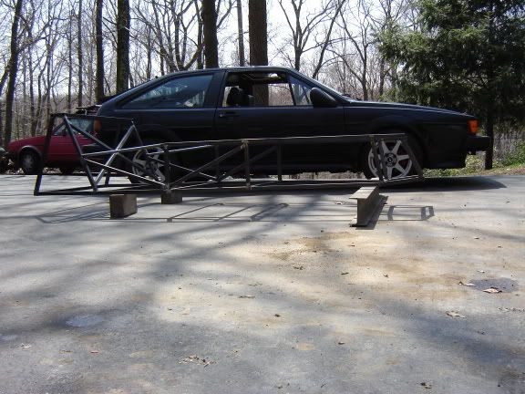
...unfortunately, the cockpit of my book-sized frame is just over 54"

Image


The way the torque tube is made has a space of about a foot from the input flange, up to the first bearing.

Image


There's also about 4.5" from the rear end of the tube up to the rear-most bearing.

Image


I was originally considering shortening both the front and rear of the tube, for a total of ~16" reduction in length...and I may still need to(I won't know for certain until I have the engine/bellhousing/tube/trans all mocked up into place), that would have put the bellhousing right in the same location as a normal transmission & still left the rear mounted transaxel in the correct place. But since I'm using the VW 1.8L which is only 18" long from the front of the pulley to the rear of the crank, and the 924 bellhousing is only 6" long, I think I'll be OK just shortening the torque tube by the 12" on the front. Yes, that will put the weight of the engine more towards the front - but w/the rear mounted transaxel my weight bias will likely be skewed toward the rear anyway. And yes, that will give me a higher polar-moment than a *normal* locost....but such is the price I pay for being a cheap-skate. :lol: But at least I'll have wide footwells if this works out!

Anyway, I started by grinding out the weld for the front mounting flange. Once I got to the point it was cracking, I just used a BFH for final removal.

Image


It's hard to tell from this pic, but the weld penetrated far enough into the plate that there was a ridge that needed removed.

Image


From the front side it was apparent that the plate wasn't welded fully through, so I made a couple trial cuts w/a hacksaw to determine how deep the welds were.

Image


From there, I used my angle-grinder to remove metal from the back side until the weld was removed.

Image


This shows the first bearing inside the tube. The 924 uses a pilot bearing for the shaft which would explain why this bearing is so far back.

Image


I used a pair of hose clamps & my scribe to mark a circle for the cut.

Image


The angle-grinder cut right through the tube & was right on target.

Image


I again used the angle-grinder...at an angle...to cut through the shaft. I was surprised at how soft the shaft was - I cut right through in ~30-seconds. I actually cut off 3-pieces: the front splined section & 2-other pieces to practice rewelding them back together.

Image

Image


I talked to about a dozen people about what would be the best way to shorten the shaft. The general opinion was there are 3-ways: I could cut it off & respline it...but I'm not equiped to cut splines & didn't want to have to find/pay a shop to do it. I could cut both ends to a taper & reweld. Or I could sleeve the shaft w/a tube & weld it on. I chose to do both of the last-2. First I clamped the shaft together w/a piece of angle iron.

Image


Then welded(this was after the first pass, I went back around & re-welded, then ground down the welds).

Image


I was fortunate that the same tubing I used for the front diagonal braces also had the perfect I.D. to sleeve the shaft. After the sleeve was fully welded, I once again ground down the welds at both ends to smooth/balance the shaft.

Image


I was a bit surprised by how true it ended up. I used the grinder to spin the shaft up to speed & didn't notice any vibration. There is a very slight visual wobble at the very end, but with the clutch disk installed, there isn't any eccentric movement of it. I also plan to take the tube over to a friend's this week to use his torch to try & remove the tail housing, so I'll just heat the shaft a bit & try to shrink it into alignment while I'm there.


The last task was to weld the front flange back into its new location. I used a square, level, and hammer to tap it on in the correct position. I then tacked it into place on 4-sides to keep it square before welding it fully.

Image


Honestly, I was a bit surprised at how easy a task this was & I'm surprised that no one else has documented this before.....of course, it's going to be a long time before I ever get to find out if it's actually going to hold together & work! :lol:


Top
  
Reply with quote  
 Post subject:
PostPosted: June 5, 2006, 1:36 pm 
Excellent progress! Love the updates! The torque tube build looks like its going to be very unique.


Top
  
Reply with quote  
 Post subject:
PostPosted: June 5, 2006, 2:31 pm 
Offline

Joined: August 15, 2005, 10:13 pm
Posts: 7043
Location: Charleston, WV
Great job Pete!


Top
 Profile  
Reply with quote  
 Post subject:
PostPosted: June 7, 2006, 3:34 pm 
Cool!


Top
  
Reply with quote  
 Post subject:
PostPosted: June 8, 2006, 5:08 pm 
(Hmmm...not sure why a couple of the pics aren't working. They seem fine if you go to the url & the code looks OK???)


Finally got some time to work on the Pocost some more....after spending most of Monday & Tuesday changing the power steering pump on my neighbor's Voyager...ugh. At least the one good thing was that we'd run out of options trying to install the new pulley on the new pump, and since all the local shops were closed, my neighbor & I decided to build a small press out of some scrap steel & an old bottle-jack I had, so at least I got a usable tool out of the job!

Image


I got the VW engine unloaded from my truck(finally)& put it on the scales. It weighs right at 250lbs w/everything on it.

Image


I tried fitting up the 924 bellhousing. As you can see, I'll need to do some rearranging! I think a VW fox oil filter mount *may* give me enough room, but for now I just removed it completely. Luckilly that cooling line is just for the heater, so it was quickly trashed as well.

Image


I ended up w/one of the bolt holes lining up perfectly. There's one other that I may be able to clearance enough to work, and there's also the option of either drilling/taping into the block for the top right bellhousing hole, or possibly making a bracket using the top-2 block holes.

Image


I went ahead & test-fit the drivetrain into the frame. It looks like I'll be fabricating an intake, but that's OK since I'm missing most of the CIS injection bits & was planning to either carb or MS it anyway.

Image


At least there's enough room at the front of the engine.

Image


I also checked the torque-tube & transaxel for clearance, but before I could get too serious about that, I had to fab/install the engine bay braces & start working on the trans tunnel.

Image


I chose to do a pretty conventional tunnel - just in case I decide to go to a normal engine/trans layout in the future - but I did angle the 2-braces on top to be parallel to the lower tunnel braces.

Image


I kept working rearward along the floor. Since the transaxel from the 924 is so long, the front of it is actually going to be in the passenger's compartment. Luckilly, I'm short & have already checked that I'll have enough leg room. I also don't think I'll buy seats, rather just make something for the cockpit w/some rollbar mounted headrests.

Image


Because of this, I had to change things on the rear bulkhead. O3 is much higher than either the book, or the Rorty plans, so I'm going to install the diagonal braces downward from the ends of O3 inward to where the lower control arm mounts will attach(I'll use the Rorty design, only widened slightly to accomodate the 924 trans). This will also let me attatch the upper arm mounts from the same diagonal braces, and I can eliminate the 3/4" vertical tunnel braces, and just angle the tunnel up to O3.

Image


One last pic showing how far the trans will intrude into the bulkhead area. Next step is finishing the bulkhead & tunnel, then I can start on the rear suspension & trans *cage*. One think I will have to plan around - both the torque-tube & transaxel are going to have to be installed from the rear of the car...which means I either have to install/remove them w/o the rear aluminum panel, or I need to design some type of access into the panel first!

Image


Top
  
Reply with quote  
 Post subject:
PostPosted: June 11, 2006, 11:39 pm 
Another update to finish off the weekend - and my 2-week vacation... :cry:

I finished up the tunnel Friday night. Originally, I wasn't going to do a full tunnel since I'm using the torque-tube & don't see much need for it, but I though I should keep my options open just in case.

Image


This shot gives an idea of the extra width I put at the rear of the tunnel to clear the trans. I did try sitting in it afterward & still had plenty of room.

Image


Here you can see where I had to get creative. Basically, I took the bottom from Rorty's plans, but widened them 1" to clear the 924 trans. Next I brought diagonal braces up from the rear of that assembly to meet the rear bulkhead, then installed the short tubes for the upper arm mounts. I did a trial fit of the trans, and now that I know I'll have room I'm going to install the diagonal braces at the rear of the lower arm mounts like Rorty's design. I'll use the trans mounts to triangulate the rest of the assembly, saving the need to run diagonaly braces up to the center of the bulkhead.

Image


After that it's just a matter of forming the round tubing for the upper & lower boot, and adding the mounts for the rollbar, then structurally everything should pretty much be finished!


Top
  
Reply with quote  
 Post subject:
PostPosted: June 12, 2006, 4:01 pm 
Offline

Joined: August 15, 2005, 10:13 pm
Posts: 7043
Location: Charleston, WV
Isn't there a crossflow head that will bolt to that block? I'll bet you could find one really cheap that may make things easier. Easier than fabbing up your own intake.


Top
 Profile  
Reply with quote  
 Post subject:
PostPosted: June 12, 2006, 4:43 pm 
Offline

Joined: March 10, 2006, 12:48 am
Posts: 294
Location: CT
Here's where it helps to be a resident watercooled VW nerd. There are 3 crossflow heads, a 2.0 liter 8 valve and the 1.8 and 2.0 liter 16 valve heads. I have heard of people putting the 1.8 8 valve head on the 16v lower end to get a compression ratio of 12:1 or higher. The inverse must then be true, so in theory you could put a 16v head on the 8v lower end and get a low compression, around 8:1. That doesn't do you any good unless you are boosting.

The 2.0 liter 8v is an engine I have no exprience with, so my knowledge is pretty limited. I know its a crossflow, but since these engines are so abundant, it would most likely be easier to swap in the whole engine. These came in almost all VWs models starting in 1992, engine code ABA.

PS, if you need any CIS parts, I should still have most lying around from my old 8v GTI, it was an 87 so it was CIS-E.

Its good to see progress, I am excited to see how well the engine and tranny work together. Have you started looking for a flywheel solution yet?

-Andy


Top
 Profile  
Reply with quote  
 Post subject:
PostPosted: June 13, 2006, 9:22 am 
Thanks Andy!

Yes, I found someone who had a flywheel from an Audi(200 IIRC), I believe it's the same as a Fox. $30 shipped, it should work fine.

I'm trying to keep the fuel system as cheap as possible. I'd briefly thought about something like a weber carb setup, but one look at prices on Vortex was enough to make me forget about that. :shock: I'd megasquirt it, but honestly I think that will be too expensive for me to make it under the GRM challenge budget, so I'm back to looking at trying to make the CIS work....

So what CIS parts do you have? I need injectors for certain. I have the fuel distributor from the 924, but I have no idea if it will work for this engine. I also need a fuel pump - I'm actually wondering if I can get away w/just the inline pump if I have a tank that drains out the bottom. There's also a piece missing off the intake - it's on the opposite ende from the TB, looks like a small sensor or something that was held in w/a couple small bolts.

Do you have any other ideas what might work? Are there any other decent carb options that could be found(manifold & carb)for under $200 or so?


Top
  
Reply with quote  
 Post subject:
PostPosted: June 13, 2006, 10:02 am 
Offline

Joined: August 15, 2005, 10:13 pm
Posts: 7043
Location: Charleston, WV
Out of pure curiousity I looked on car-part.com and there were over 50 pages of 2.0 liter crossflow motors listed. (I searched for a 97 Golf) There were a few pages of them under $150 that said things like "runs great" etc. I'll bet if you shop around you could find someone who would sell you the engine, harness, and ECU for around $200. Just something to think about.


Top
 Profile  
Reply with quote  
 Post subject:
PostPosted: June 13, 2006, 10:53 am 
That's a thought, but I've always heard the 2.0L is even taller than the 1.8L - which was one of the reasons people do the ABA swap...or at least, that's what info I've deciphered from the 2-gazillion threads about it on the Vortex. :roll:

There's a dellotro carb/manifold setup on ebay now starting at $200, but it looks like it would probably need rebuilding. However, a quick google for "Dellotro rebuild kit" didn't find any relevant links, so I'm wondering if parts are available for them. I know the mikuni's on my old Colt were getting difficult to find parts for.


Top
  
Reply with quote  
 Post subject:
PostPosted: June 13, 2006, 5:38 pm 
Offline

Joined: March 10, 2006, 12:48 am
Posts: 294
Location: CT
I couldn't get the injectors out of my old 8v, so unfortunately I don't have them still. I have the airbox/fuel distributor that came with the car, and I also have the wiring harness that is mostly uncut. I had to cut a few small wires under the dash. I don't have the ECU's anymore, I wasn't planning on ever needing them again, but I do have spare 16v ECUS. For a fuel pump, you can get away with a single inline pump, but it needs to be able to put out like 85 PSI.

Personally, I would look into doing up a carb because CIS is a pretty awkward fuel injection system. A mechanical system with electrical overrides. Have you considered bike carbs? I know they are cheap, but I'm not sure how well they will work.

Oh, for a distributor, if your's isn't a vacuum advance model, you should be able to pick one up out of an early carbed rabbit.

Will the Audi 200 flywheel match? I never knew that. I would like to see a picture of it when you bolt it up.

-Andy


Top
 Profile  
Reply with quote  
 Post subject:
PostPosted: June 13, 2006, 10:43 pm 
Will the 16V ecu work w/an 8V engine?

I've thought about bike carbs...but haven't gone any further than that. lol

I do have the igniton distributor for the GTi, but not the fuel distributor.

Yeah, the Fox/Audi clutch is actually the same flywheel & clutch disk as the GTi w/a *normal* p-plate. I'll definitely be taking pics of the whole process.


Top
  
Reply with quote  
 Post subject:
PostPosted: June 14, 2006, 7:23 am 
Offline

Joined: March 10, 2006, 12:48 am
Posts: 294
Location: CT
Yes, an 8v will run on a 16v ECU. I know this because when I was trouble shooting my 16v Scirocco, I swapped its ECU into my then 8v GTI.

A pic of the 3 toys.
Image

My fuel distributor is CIS-E, so it has the potentiometer and differential pressure regulator attached. I don't know what CIS came with. I also have the knock sensor control unit. I was thinking about it, and using the wiring harness I have probably wouldn't be too hard, because all you would have to do is put power where you need it via an ignition switch and a relay, all the wires running into the ECU are uncut. But, the biggest problem I can think of is the airbox's size, and where can you put it? The engine you have should have the throttle body towards the rear because it is an A1 engine, so maybe you could fit the box infront of the firewall.

The reason why I was asking about a flywheel and pressure plate is because the one's I have seen so far look very different from traditional units. On the VW transmissions I have worked with, late 80s, the clutch is engaged and disengaged by a rod that slides in the input shaft of the tranny. If the Porsche is the same, then it isn't going to be a problem, but if it is more traditional, then I'm lost on what to do.

-Andy


Top
 Profile  
Reply with quote  
 Post subject:
PostPosted: June 14, 2006, 9:56 am 
Nice pic! I gotta get me another dub someday... I like the way you did the rear of the locost too - nice simplification of the tubes.

Yeah, when I first looked at the GTi clutch I wondered how the heck I was going to make it work. Someone on the vortex suggested the Fox/Dasher/Quantum clutch & it works great.

What do you want for all your CIS parts?


Top
  
Reply with quote  
Display posts from previous:  Sort by  
Post new topic Reply to topic  [ 81 posts ]  Go to page Previous  1, 2, 3, 4, 5, 6  Next

All times are UTC - 5 hours [ DST ]


Who is online

Users browsing this forum: No registered users and 42 guests


You cannot post new topics in this forum
You cannot reply to topics in this forum
You cannot edit your posts in this forum
You cannot delete your posts in this forum
You cannot post attachments in this forum

Jump to:  
POWERED_BY