LocostUSA.com

Learning how to build Lotus Seven replicas...together!
It is currently April 18, 2024, 1:53 am

All times are UTC - 5 hours [ DST ]


Post new topic Reply to topic  [ 373 posts ]  Go to page 1, 2, 3, 4, 5 ... 25  Next
Author Message
PostPosted: September 3, 2014, 10:10 pm 
Offline
User avatar

Joined: August 18, 2014, 11:20 pm
Posts: 185
Location: San Antonio, Texas
Gents,
After much discussion with the wife, I have recieved the green light to proceed with building my homemade performance sports car. The primary goals are to keep the build cheap (and I mean cheap), reasonably light, and sturdy. My approach to car is to use ALOT of the components which I already have, and make purchases very sparingly.

In terms of my background, I work as a mechanical engineer at an engine performance and development company in Texas (doing engine testing, in-cylinder pressure data gathering/analysis, engine calibrations, etc...), 4 years experience in FSAE (for 3 cars), and 1 year of Mini Baja. ~4 years of Virginia region SCCA Autocross (DP, and SM class) and past Nissan mechanic, and long time bicycle mechanic (8 bike shops).

Sadly, this engineering desk job is deminishing my fabrication skills, and many moons have passed since I wrote codes for CNC machining for FSAE parts. And consequently, I'd like to keep this build caveman simple.

Goals:
1300 lbs
265ish hp
(4.9 lbs/hp)
$2,000 budget

I've decided to build a Middy Lotus 7-ish car powered by a 2L B18 engine, using a 1990 Acura Integra front subframe and suspension members, and a NA miata front subframe and front suspension members.

Weightwise, this may be challenging as:
front subframe: 16lbs
Pass side sub frame: 28.3lbs
rear subframe: 20lbs
driver side subframe: 31.7lbs

Subtotal: 96lbs

The front and rear subframes will be joined with four mild steel 2"x3" rectagular tubing above the subframes (3" sides placed vertically), and two 1"x1" square tubing below the subframes, which will form the spine of the car. Mild steel AISI 1020 intended (4130 is simply out of the budget, and I don't intend on approaching the yeild strength of the cheap 1020 stuff, and Youngs' Modulus is the same for 1020 and 4130). I'll be using my old faithful Lincoln SPT-135 MIG welder with Argon/CO2 shielding gas mix. Sorry, no showcar TIG work here.

I already have a 1-3/4" dia round tube main roll hoop from AISI 1020 with a triangulated rear X-brace (which is way overbuilt and intented for a 2500lb car), which will tie into the chassis in six locations:
X2 Roll hoop to Lower (Primary) Frame rail spine
X2 Roll hoop to chassis waist
X2 Rear X brace to upper shock tower/upper A-arm mount
weight: 68.5 lbs

The 2"x3" longitudinal rectangular lower box members will be in bending, and the upper 1"x1" square tubing from the roll hoop forward will be in compression. Rearward of the integra subframe, a removeable triangulated X-brace will tie the upper control arm pickup points, ala aerial At-om inspired. I intend to keep the car forward of the roll hoop very much Lotus 7-inspired.

With regards to vehicular motivation: Honda B series.
Why use a Honda B18? Simple. I've poured a foolish amount of money into building my 85mm bore B18A1 with Darton Sleeves, 12.5:1 CR JE Pistons, Manley 4340 Rods, Skunk2 Pro3 Cams, Skunk2 Pro valvesprings, Skunk2 titanium retainers, Skunk2 Pro intake manifold, match ported head, 76mm throttle body, yada yada yada, blah blah blah... In short, it revs to 9.5k, has measily torque, and makes ~265hp at the wheels.

For the transmission, likewise, more money was foolishly spent on a cable type GSR YS1 short ratio transmission with 4.4 final drive, rebuilt with sychrotech internals, an MFactory Multi-plate clutch pack adjustable 1-way LSD. For middy usage, I understand I will need to modify the transmission end of shifter linkage into a J-shape, with a U-joint on the selector shaft input.

Why an Acura Integra front subframe and suspension members? Primarily because this would save me alot of fabrication time and money, as the suspension geometry is already figured out, as lower control arm/radius rod, and upper wishbone have very good camber control, very little bump steer, and a VERY large Factor of Safety built into the design. The outboard pickup point on the upright is located outside and above the tire, which isnt very conducive to compact suspension packaging. I intend on cutting the upright/knuckle as far needed to clear the 16" wheel, and then cut a vertical 3/4" slot into middle to accomodate a spherical rod end bearing from the upper control arm. No fancy push rod suspension for the rear, just direct actuation from the factory LCA.

Why a NA miata front subframe, suspension arms, and steering rack? The miata already has very well sorted geometry and camber curves. Also the miata subframe and suspension designed to support a 2000+lb car, thus factor of safety for a 1500lb car will go up. More or less, the same reasons as mentioned above.

The current issue I see with using the front miata suspension/subframe, is that the factory upper shock mount is placed upwards and outboard. The two solutions I see are the following:
Use a very short shock body, and attack the upper shock pickup point in between the upper wishbone arm. (Essentially use a motorcycle rear spring/damper). Pros: Simple and reduced number of components. Cons: cost of new springs/dampers.
Use a pushrod and bellcrank setup, and place the dampers within the front subframe. Pros: adjustable rideheight by varying rod length by not removing damper travel. Reduced polar moment of inertia in roll. Adjustable installation ratio by virtue of bellcrank design. Can still use current springs/dampers. Cons: Increased overall weight and complexity. Increased packaging difficulties with radiator and spring/dampers. Increased fabrication time. More suspension analysis and design required--Adams, Optimum K, etc...

Shape of the Car/Body:
I would like to place two small motorcycle radiators (in series) (or a Griffen 19"x22"x3" radiator) within the front subframe, followed by a 10 gallon fuel cell rearward of the front subframe, followed by my optima battery.

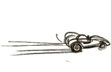
Essentially, replicate front and middle dimensions generally speaking, of the Lotus 7, with the beautiful long slender bonnet, however with a battery and longitudinal fuel cell, in place of where a longitudinally mounted rover engine would have traditionally been. I plan on trying my best to copy the shape and paintjob of a caterham r500.
Attachment:
IMG_3655.JPG

The nosecone would be standard issue Lotus 7. The goal for the car is to NOT have high placed tubes forward of the main roll hoop, with the upper waist of the chassis barely chest high whilst the driver is seated. car will have no windshield, no roof, no doors. The bodywork behind the rear subframe would quickly terminate at a sharp angle. The seating placement would be more forward than a traditional Lotus 7, thus to maintain the slender bonnet style the wheelbase would be slightly increased. This is not necessarily a bad thing, as a ~6" longer wheelbase would be more conducive to stability, and a slender and centered longitudinally placed fuel cell would aid in transitional handling.
I would like to run 1.75" dia aluminum tubing within the longitudinal 2"x3" frame rails, with 90 degree bulkhead fittings at the frame enterances and exits.

To itemize the components that I already have, and components which I would need to purchase:
Currently have:
Acura Integra subframe
Acura Integra front suspension arms
Eibach Springs/ Koni/tokico Dampers
Honda B-series engine (Complete w/wiring harness, manifolds, ECU, starter)
B-series transmission (Complete w/ clutch cable)
Clutchmasters Kevlar Clutch w/ heavy duty pressure plate
Integra Type R flywheel
B-series shift linkages, and shift lever w/knob
Acura Integra pedals (top swing)
Left and Right axles w/ halfshafts
left and right knuckes
Wilwood Dynalite 4-piston brake kit w/ 12.2" rotors, and Aluminum hats
1-3/4" dia Main Roll Hoop (AISI 1020) w/ rear X-brace, and lateral member for harnesses
Kosei K1 16x8" wheels
Yokohama A048 tires 225/45R16
Momo Start Seat
Momo steering wheel
Simpson 5pt harness
Optima Red Top battery w/battery box and 20 ft of battery leads
OEM integra fuel pump and fuel lines

To buy:
Miata front subframe
Miata front suspension arms w/knuckles
Miata steering rack and tie rods
Miata steering shaft
(Miata parts total: $600)
Wilwood Caliper bracket for NA Miata knuckles ($100)
Aluminum Sheet for body panels: ($250)
60 ft of 2"x3" tubing AISI 1020 ($200)
100 ft of 1"x"1 AISI 1020 ($100)
20 ft of 1.75" diameter 6061-T6 aluminum tubing ($40)
Griffen 19"x22"x3" radiator ($173)
X2 Spherical Bearing rod ends (1/2" ID) ($30)
X4 Yamaha R6 Shocks used: $200
brake lines ($150)
fuel lines ($100)
Headlights, turn signals, brake lights, horn ($100)
side mirrors, rearview mirror ($50)

RCI Fuel Cell 8 gal: $90
http://www.summitracing.com/parts/bob-10993/overview/

Also, out of curiosity, as well as trying to be somewhat considerate of the weight of each of the parts, I've weighed the parts which I've cannibalized from the integra:


Roll Bar: 68.5
Wheel/tire: 37.3 (x4 149.2)

front subframe: 16
Pass sub frame: 28.3
rear subframe: 20
driver side subframe: 31.7

Subtotal: 96


radiator: 11
wilwood dynalite caliper: 4.1 (x2 8.2)
wilwood 12.2" rotor and hat: 10 (x2)

optima red top battery: 33.3

pass side axle: 14
drivers side axle: 14

steering column: 8.9
steering rack: 23.4

upright, upper arm, lower arm, and radius rod: 30.6 (x2 61.2)
master cylinder: 2.2
brake booster: 8.5
pedal box assembly: 9.9

header: 17
exhaust muffler: 20.6

seat and bracket: 25.7
steering wheel and adapter 3
seat belts: 4.7
koni shock +eibach spring+fork: 11.8 (x2 23.6)
tokico shock + eiback spring: 10.6 (x2 21.2)
shifter linkages +knob: 6

intake arm: 3.7
catch can +hoses: 5.7

Engine/Trans: 350lbs (est)

subtotal: 1009.5 lbs


I'll try to post pics of the madness once I start cutting metal.
-Andrew


You do not have the required permissions to view the files attached to this post.

_________________
There is no such thing as mechanical failure, only a lack of attention to detail.


Last edited by LateralScience on September 14, 2014, 1:38 pm, edited 1 time in total.

Top
 Profile  
Reply with quote  
PostPosted: September 4, 2014, 12:09 am 
Offline

Joined: October 19, 2009, 9:36 pm
Posts: 2199
Location: meadview arizona
yep, we all started with a budget like that.

_________________
this story shall the good man teach his son,
and chrispin chrispian shall ne'er go by,
from this day to the end of the world.
but we in it shall be remembered.


Top
 Profile  
Reply with quote  
PostPosted: September 4, 2014, 5:45 am 
Offline
Toyotaphobe
User avatar

Joined: April 5, 2008, 2:25 am
Posts: 4829
Location: Fort Worth, Texas
Sounds like a plan. You need a plan. Most any plan will do.

I was doing some writing tonight, or is it morning, and came to the realization that for most of us this is the adventure in life we've wanted since we were kids. You read about adventures and want to have one, but don't know how to go about it and we never seem to get placed in those Indiana Jones types of situations.

We have this desire to do it our way and suddenly we're smack dab into the adventure of our lives and don't even realize it.

Enjoy the journey.

I understand your rationale and applaud you, but be prepared to make major changes in the path you've taken as you learn more about the finicky little details of building a car.

I like using car subframes, but most here don't do it. Why? It turns out it's not all that hard to build your own and there are advantages to that. Plus you can make it look better and the packaging issue isn't all that hard either, especially when you have a model to follow.

It's kinda like an At-om bomb. It was considered almost un-doable until it was done. Now they worry people will build one in their garage.

_________________
mobilito ergo sum
I drive therefore I am

I can explain it to you,
but I can't understand it for you.


Top
 Profile  
Reply with quote  
PostPosted: September 5, 2014, 12:03 am 
Offline
User avatar

Joined: August 18, 2014, 11:20 pm
Posts: 185
Location: San Antonio, Texas
Mocking up the bits and bobs:

Attachment:
Mockup.jpg

(Is it too early to sit in the seat and make car noises?)

Front View:
Attachment:
Frontview.jpg

(Note I am thinking of shortening the height of the main roll hoop, as well as tie it in to the longitudinal subframe box members. One concern I have is the main roll hoop is too wide to be directly infront of the longitudial subframe members. Reducing the width of the main roll hoop requires cutting and sectioning the 1-piece roll hoop--which is a BIG no-no in SCCA and NASA if I am not mistaken.)

Donor Car:
Attachment:
Donor Car.jpg


Well...it has been many moons since my welding class in college, and I may be a bit rusty:
Attachment:
Welding practice1.jpg


carguy123, I definitely have thought about fabricating the entire chassis from scratch, as well as A-arms and pushrods. However I'm concerned my engineering OCD will kick in, and I'll be working on 1 A-arm for 3 months, making a jig for a jig, and then feel compelled to build a Matlab simulation to analyze the endless degrees of freedom in roll, pitch, yaw, warp, etc...

In formula SAE I designed the inboard pullrod suspension system locating the bell crank and spring/damper under the chassis and between the splay of the A-arms for both the front and rear. The design reviews, and headaches associated with the design was a monumental pain. I recall we spent $2,000 on 4130 tubing, and another $2000 for Cartesian Company to CNC notch our model. We spent atleast $3000 on a steel chassis jig table, along with a FARO Arm for CMM of chassis nodes and pickup points. In the end, what we found to make the car really fast at an autocross was suspension tuning, and seat time.

In FSAE we got so bogged down in suspension design, analysis and testing, we forgot to have a solid engine team. I'm afraid I'll fall back to tire testing with live IR temps, slip angle testing with Corrsys-Datron sensors, 16 accelerometers placed at chassis nodes, and then I'll start renting out rooms in my house to buy PCB triaxial accerometers.
(Anyhow, sorry for the tangent.)


My goal is to keep this build caveman simple, and very inexpensive.

There are a few things which I will modify in order to lower the chassis:
-Move inboad LCA a upwards (box tubing to accept inboard LCA bushing)
-Cut uprights below upper wishbone pickup point
-Drill 5/8" hole through upright to allow for lower placement of AFCO tubes/heim joints (creating an upper A-arm with camber adjustment)


I'm am most certainly open to criticisms, as there are alot of very talented folks here.

-Andrew


You do not have the required permissions to view the files attached to this post.

_________________
There is no such thing as mechanical failure, only a lack of attention to detail.


Top
 Profile  
Reply with quote  
PostPosted: September 7, 2014, 9:45 pm 
Offline
User avatar

Joined: August 18, 2014, 11:20 pm
Posts: 185
Location: San Antonio, Texas
Gents,

It appears sourcing a miata front subframe, and front A-arms is proving more difficult than I anticipated. I can source one from ebay, but that's not proving to be very cost effective. Salvage yards are empty, and folks selling miata parts online think they are selling gold.

Therefore, I've changed paths, and I've built a 4ft x 8ft table from maple hardwood, and sourced 150 ft of 1" square of mild steel tubing (16 gauge), and I've begun construction of the standard Locost 7 Book Chassis:

Bottom Rail Completed:
Attachment:
bottom rail.jpg


Adding uprights:
Attachment:
table and bottom frame.jpg


Laser Alignment:
Attachment:
Laser Alignment.jpg


Blocks before tac weld:
Attachment:
blocks before tac welds.jpg


closeup on fitting tubes:
Attachment:
closeup on fitting tubes.jpg


I intend to ONLY tac weld the chassis together once all of the tubes are cut and verified for length and angle. My intention is to still have the chassis forward of the main roll hoop standard issue Locost 7 book chassis--nothing special.

I'm playing with the idea of using the engine/trans as a semi-stressed member, and direct suspension loads to the engine mounts. Any thoughts on this? I think this would be awesome, however a clutch dump inducing an impulse load to an aluminum block would be scary. I may need to highjack a copy of ANSYS to ensure a sufficient factor of safety.

--Rear LCA to rear engine mount.
Attachment:
rear lower LCA.jpg


My other thoughts were:
--Rear Upper control arm to transmission mount.
--inboard radius rod pickup point to triangulated node on Locost bottom rail

Also, does anyone have suggestions on building a cost effective tube bender and chassis rotisserie?

Thanks!
-Andrew


You do not have the required permissions to view the files attached to this post.

_________________
There is no such thing as mechanical failure, only a lack of attention to detail.


Top
 Profile  
Reply with quote  
PostPosted: September 8, 2014, 11:19 am 
Offline
User avatar

Joined: October 19, 2012, 9:25 pm
Posts: 3365
Location: Summerville, SC
Put away the laser and your life will get a little better.

Your tube fitment is excellent, get comfortable with small gaps early on and your life will get a little better.

Keep it simple and you'll complete your build. Analyze it to death and one day I'll probably complete your build. :wink:

Tight lines :cheers:

_________________
Too much week, not enough weekend.

OOPS I did it again
http://www.locostusa.com/forums/viewtopic.php?f=35&t=17496

Blood Sweat and Beers
http://www.locostusa.com/forums/viewtopic.php?f=35&t=15216


Top
 Profile  
Reply with quote  
PostPosted: September 8, 2014, 12:38 pm 
Offline
Mid-Engined Maniac

Joined: April 23, 2006, 8:26 pm
Posts: 6418
Location: SoCal
Before anything else is done in the rear bay, the rear suspension geometry needs to be figured out. It'll do little good to build the frame around the engine only to find that the stock A-arm pivots have to go where the engine block is.

And I vote against using the engine as a stressed member - the vibration will be crazy.

_________________
Midlana book: Build this mid-engine Locost!, http://midlana.com/stuff/book/
Kimini book: Designing mid-engine cars using FWD drivetrains
Both available from https://www.lulu.com/


Top
 Profile  
Reply with quote  
PostPosted: September 8, 2014, 6:31 pm 
Offline
User avatar

Joined: August 18, 2014, 11:20 pm
Posts: 185
Location: San Antonio, Texas
My initial plans were to use the factory integra subframe, cut the upright and machine a slot for a heim joint, and use afco swaged suspension links to follow the directions of the lower control arm and radius rod. There's just not enough room for a standard upper A-arm on the drivers side. The locations of the inboard pickup points would be the same direction (just shorter) as the lower arm and radius rod, however lower to allow for a slight 10-13 degree inward slope of the upper a arm. The axles will be horizontal.
The factory LCA will be horizontal, but with the inboard pickup point to be raised, such that upon lowering the entire car the lateral jacking forces while cornering will not induce a pro roll vertical downward force on the chassis.

In fsae 2009, we used a cbr 600 f4i engine as a semi stressed member. But the impulse loads from that car were much less compared to a 2 liter 1300 lb car.
In fsae 2012 we used a single cylinder wr450f, which indeed induced violent loads to the rear basket, and we tore out engine mount tubes very regularly.

When I built this 2 liter B-series a year ago I painstaking balanced the rods, wrist pins, and pistons within 0.1 grams of each other. I had the crank balance separately. Needless to say, the engine runs very smooth. It's the suspension loads directed to block which scare me.

_________________
There is no such thing as mechanical failure, only a lack of attention to detail.


Top
 Profile  
Reply with quote  
PostPosted: September 8, 2014, 10:19 pm 
Offline
User avatar

Joined: April 19, 2012, 9:43 pm
Posts: 419
Location: Colorado
Don't risk your very custom and very expensive engine for a few pounds saved. How much would you cry if you cracked your block and ruined it on the first serious pothole you couldn't manage to avoid? Bent and cracked frames can be cut and fixed. An engine block... not so much.

I vote you build a frame around that beautiful engine to carry loads and let the engine do what it does best: spin tires.


Top
 Profile  
Reply with quote  
PostPosted: September 8, 2014, 11:07 pm 
Offline
The voice of reason
User avatar

Joined: January 10, 2008, 4:47 pm
Posts: 7652
Location: Massachusetts
Quote:
It's the suspension loads directed to block which scare me.


They should. It doesn't seem worth it to me unless it makes a difference like being able to get the motor out of the car without a hacksaw. That type of thing happens on little formula cars, but shouldn't for us.

It doesn't really matter how well you balance your engine, an inline 4 is inherently unbalanced because the connecting rods are not infinite length. On my formula ford, I expect it is well balanced but I get double vision while it is idling. I don't mind in that car and somehow I manage to see while actually on the track, but I don't think I would like it for any street use, at least not at stop lights...

Quote:
The factory LCA will be horizontal, but with the inboard pickup point to be raised, such that upon lowering the entire car the lateral jacking forces while cornering will not induce a pro roll vertical downward force on the chassis.


I'm a little confused. Jacking forces are vertical, that's why they are called jacking forces. When lowering the entire car do you mean using smaller diameter tires? A vertical down force would be neither pro or anti roll.. I just don't understand, perhaps you can go a little slower thru this...

_________________
Marcus Barrow - Car9 an open design community supported sports car for home builders!
SketchUp collection for LocostUSA: "Dream it, Build it, Drive it!"
Car9 Roadster information - models, drawings, resources etc.


Top
 Profile  
Reply with quote  
PostPosted: September 9, 2014, 12:09 am 
Offline
User avatar

Joined: August 18, 2014, 11:20 pm
Posts: 185
Location: San Antonio, Texas
horizenjob, imagine a lower control arm oriented such that the inboard pickup point on the upright is lower than the outboard pickup point on the chassis. A lateral force acting on the tire will transmit that lateral force to the upright, and likewise the lower control arm.

If we decompose the resultant vector acting on the lower control arm:

The horizontal control arm drawn on the left has zero vertical component vector. The lateral force acting on the tire is equal to the lateral force acting on the chassis. The angled control arm on the drawn on the right has vector Fz acting on the chassis, in which Fz= sin(LCA angle)*LCA force. This vertical component is what induces downward jacking forces.
Attachment:
jacking forces.jpg


If you flip the orientation, and place the inboard chassis point above the upright point, this induces an upward jacking force.

Note that this orientation can often be transient, in that if the spring attached to the chassis is still compressing while the car is cornering, you have to "wait" for the spring to finish compressing before lateral tire force can fully act on the car.


You do not have the required permissions to view the files attached to this post.

_________________
There is no such thing as mechanical failure, only a lack of attention to detail.


Top
 Profile  
Reply with quote  
PostPosted: September 9, 2014, 1:43 am 
Offline
The voice of reason
User avatar

Joined: January 10, 2008, 4:47 pm
Posts: 7652
Location: Massachusetts
It's good you have a physics point of view. There's a lot to understand here and I am sometimes slow at it. Your car has upper and lower control arms, I think. Together they create a virtual swing arm which pivots from the intersection of the angles of the control arms. Draw a line from the tire contact patch to that virtual swing arm pivot and that will give you a force line. The angle of this line will give you the jacking forces created by that tire. Take into account the amount of weight on that tire while cornering and then you can get the actual vertical force generated.

It's late and I may have some of that wrong, but it's a basic idea. Your analysis would be correct for some older cars that had real swing arm suspensions, like Mercedes, VW and Corvair.

_________________
Marcus Barrow - Car9 an open design community supported sports car for home builders!
SketchUp collection for LocostUSA: "Dream it, Build it, Drive it!"
Car9 Roadster information - models, drawings, resources etc.


Top
 Profile  
Reply with quote  
PostPosted: September 9, 2014, 1:52 am 
Offline
The voice of reason
User avatar

Joined: January 10, 2008, 4:47 pm
Posts: 7652
Location: Massachusetts
Quote:
spring attached to the chassis is still compressing while the car is cornering, you have to "wait" for the spring to finish compressing before lateral tire force can fully act on the car.


The forces act immediately on the car. While the car rolls the suspension geometry and the force angles are potentially changing, but not necessarily so. that all depends on your suspension design. It's what makes this stuff interesting. Your not wrong exactly, but your statement is very simplified. Some things happen right away, others play out while the suspension is moving. For instance weight transfer is immediately affected by relative geometric roll stiffness of the front compared to the rear, but the elastic roll stiffness provided by anti roll bars and springs does not fully come into play until the car rolls.

_________________
Marcus Barrow - Car9 an open design community supported sports car for home builders!
SketchUp collection for LocostUSA: "Dream it, Build it, Drive it!"
Car9 Roadster information - models, drawings, resources etc.


Top
 Profile  
Reply with quote  
PostPosted: September 9, 2014, 4:12 am 
Offline

Joined: October 19, 2009, 9:36 pm
Posts: 2199
Location: meadview arizona
the problem here is that you haven't seen enough real life stuff but have emersed yourself in data.

i will ask a question, if a spring is attached to the chassis at one end and the other is attached to the wheel in a vertical plane, when the car hits a bump and deflects the wheel up, compressing the spring, how come the car doesn't drop by the same amount.

the spring doesn't know which end to move, it just gets shorter.

the first car i ever built was in the late 60's, my friend who also contributed to the build in an equal amount though like you, tended to over complicate things, example, if you showed him a nail and asked if he could come up with a device to use the nail to join two pieces of wood together, he would have invented the pnumatic nail gun, i however would have invented the hammer.

this is a one off car, you will never have to proove the consept or have several meeting of the design commitee along with several budget meetings or consumer focus groups before the car hits the street, if you go on the way you are, you will end up with citroen style hydraulic suspension including self leveling and turning headlight with the steering and suspension.

it can be simple or complicated, complicated is expensive, simple is cheap and has probably been done before, next you will be looking at how you can better the wheel to connect the vehicle to the road because tires are too flexable.

sorry for the strong words here, but unless you stop over thinking the project it will end up being sold after a couple of years as toobusy said above. KISS!!!!

gas strut for car hoods are a good example, if i had a buck for every time a hood has fallen on my head due to these failing, i could afford the emergenct room fees for a cut head, all when a stick would do just fine.

throw away the laser and get a chalk line.

_________________
this story shall the good man teach his son,
and chrispin chrispian shall ne'er go by,
from this day to the end of the world.
but we in it shall be remembered.


Top
 Profile  
Reply with quote  
PostPosted: September 9, 2014, 8:12 am 
Offline
User avatar

Joined: August 18, 2014, 11:20 pm
Posts: 185
Location: San Antonio, Texas
John, I full heartedly agree with you. It is very easy to get bogged down in data gathering and design, and end up with a car which looks great in theory, but is crap to drive.

As I expressed in my first post, I intend to keep this build caveman simple. I've got plenty of complicated engine data at work that I analyze, that I don't want this build to look more like my work.

In FSAE 2011 our car was so bogged down with analysis we failed to do the basics well. We had spent too much time at many design reviews arguing about relavent degrees of freedom in the cars Matlab model, that we failed to do the basics well. Like clean the metal before you weld. Make sure the shielding gas is on. Tac tubes together before fully welding the chassis. Etc...

I'll be sure to throw out the laser...don't worry, I wasn't planning on borrowing a FARO arm at work.

I most certainly appreciate the feedback guys!

_________________
There is no such thing as mechanical failure, only a lack of attention to detail.


Top
 Profile  
Reply with quote  
Display posts from previous:  Sort by  
Post new topic Reply to topic  [ 373 posts ]  Go to page 1, 2, 3, 4, 5 ... 25  Next

All times are UTC - 5 hours [ DST ]


Who is online

Users browsing this forum: No registered users and 7 guests


You cannot post new topics in this forum
You cannot reply to topics in this forum
You cannot edit your posts in this forum
You cannot delete your posts in this forum
You cannot post attachments in this forum

Jump to:  
POWERED_BY