LocostUSA.com

Learning how to build Lotus Seven replicas...together!
It is currently May 3, 2024, 1:03 pm

All times are UTC - 5 hours [ DST ]


Post new topic Reply to topic  [ 424 posts ]  Go to page Previous  1 ... 22, 23, 24, 25, 26, 27, 28, 29  Next
Author Message
PostPosted: January 8, 2015, 10:05 pm 
Offline
Always Moore!
User avatar

Joined: November 9, 2007, 3:40 pm
Posts: 4076
Location: Pittsburgh, PA
Bobber wrote:
So, looking at a chassis torsional rigidity of 2400 lb per inch effective wheel rate with a sprung wheel rate of 240 lb per inch yields an effective wheel spring rate of 218 lb per inch. The chassis torsion portion is undamped.

This gives a good idea of what chassis torsional rigidity does and doesn't do.


So what about tires? Their spring rate is much lower than the chassis.

Attachment:
stick model.JPG


So the red circle is the center of mass of the vehicle and its some distance (H) above the ground. This force times this distance is what determines weight transfer as it creates a torque that the suspension has to react. How much each end of the car reacts determines whether the car oversteers, is neutral, or understeers. Assuming the front part of the chassis (the light green line) and the rear portion of the chassis (the light purple line) are the same stiffness then you can make the front suspension (dark green line) and the rear suspension (dark purple line) have the same roll stiffness and theoretically the car should be neutral if all else is equal. Now keep the front and rear roll stiffnesses the same but make the rear part of the chassis 25% as stiff as it was before. Since we're dealing with springs in series and the front is stiffer it will be seeing a higher percentage of the weight being transferred from cornering. This will cause the front to have less grip and the car will understeer. You can compensate with a higher roll stiffness at the soft end of the car (IE stiffer springs and/or larger anti roll bar) but then you would be reducing chassis compliance and its ability to handle irregularities in the pavement.

I'd worry more about this versus the chassis's contribution to spring rate. If one area of the chassis is too soft then it will limit the chassis's stiffness and make tuning difficult. We had an FSAE car that was just like this; very easy to drive but no matter what you did the car was tight.


You do not have the required permissions to view the files attached to this post.

_________________
-Andrew
Build Log
Youtube


Top
 Profile  
Reply with quote  
PostPosted: February 6, 2015, 8:45 pm 
Offline

Joined: April 15, 2014, 1:54 pm
Posts: 470
A car cannot lift a single inside wheel on a curve if the chassis is rigid. True or false?


Top
 Profile  
Reply with quote  
PostPosted: February 6, 2015, 9:04 pm 
Offline
Always Moore!
User avatar

Joined: November 9, 2007, 3:40 pm
Posts: 4076
Location: Pittsburgh, PA
False

_________________
-Andrew
Build Log
Youtube


Top
 Profile  
Reply with quote  
PostPosted: March 5, 2015, 3:05 pm 
Offline

Joined: April 15, 2014, 1:54 pm
Posts: 470
I'm supposed to be designing some electrical transmission towers and just noticed that if you have a structure (vehicle chassis) that is "A" shaped in plan, with the suspension at one end connected to the wide end and the suspension at the other end spaced a distance back from the apex of the "A" (the further the better), you transfer all torsion forces in the frame to bending forces in the legs of the "A".

Back to work.


Top
 Profile  
Reply with quote  
 Post subject: Re:
PostPosted: March 31, 2016, 12:35 pm 
Offline

Joined: March 31, 2016, 11:56 am
Posts: 1
May I ask how to get torsion stiffnes lbs-in/degrees or Nm/degrees when I do some analysis and I have only Force and deformation in cm/inches. I read it on the 3rd page of this theme but I didnt completely understand the equation members could you please explain deeper? Which distance means what?
Image 
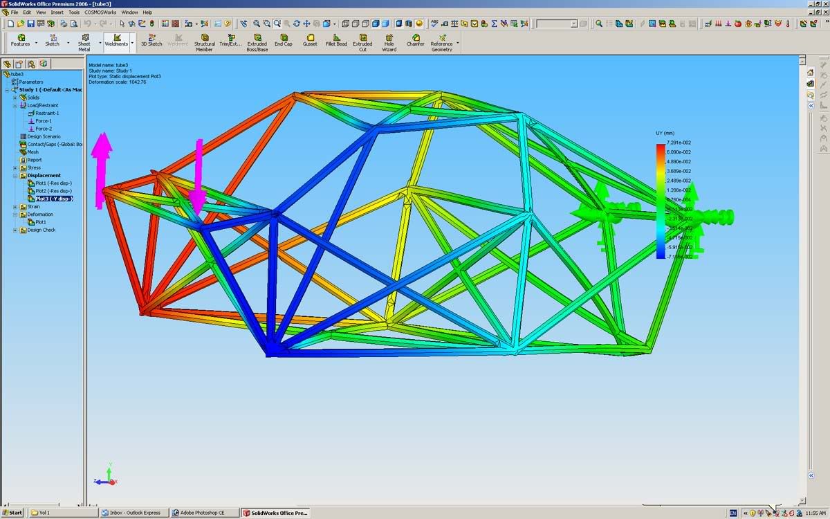
for example here are two opposite forces to simulate moment and can you explain the equation on this model please?
Please accept apologize for bad english


Top
 Profile  
Reply with quote  
PostPosted: April 18, 2016, 7:56 pm 
Offline

Joined: April 17, 2016, 11:56 am
Posts: 1
Hello, I'm new to this community, and my first post will start with a dumb question. How are compared the stifness of the differents chassis designs? Like, how much is the book, the Haynes, the 442....


Top
 Profile  
Reply with quote  
PostPosted: May 10, 2016, 1:24 pm 
Offline

Joined: April 15, 2014, 1:54 pm
Posts: 470
Valid question. I can't explain the lack of replies.


Top
 Profile  
Reply with quote  
PostPosted: May 10, 2016, 1:40 pm 
Offline

Joined: April 15, 2014, 1:54 pm
Posts: 470
I'm checking a new graphics program to see it it will submit to this site.


You do not have the required permissions to view the files attached to this post.


Top
 Profile  
Reply with quote  
PostPosted: May 30, 2016, 9:47 am 
Offline

Joined: April 15, 2014, 1:54 pm
Posts: 470
I got an update to my structural program and had to try it out. I want to see if I can post the graphics here since this site is the hardest to post graphics to. The first shot is unloaded and the second with torsion load.

This is a generic Locost chassis with no triangulation. Torsional rigidity less than 650 ft lb per degree using one inch square, 0.120 inch wall tube. The caboose hasn’t been designed yet – it adds a fair amount of lateral and hence longitudinal stiffness.
I may use this as a test bed to try ideas. I see a big need to stiffen the engine bay. Anybody want me to experiment with anything?


You do not have the required permissions to view the files attached to this post.


Top
 Profile  
Reply with quote  
PostPosted: May 30, 2016, 11:57 am 
Offline
User avatar

Joined: October 24, 2008, 2:13 pm
Posts: 5326
Location: Carlsbad, California, USA
Bob,

I have a sense that you know about the Linton Analysis. If you don't, it may provide some interesting scenarios you'd like to try yourself. Long story short, it took a commercial Locost chassis done by a company called Leugo and compared the results of FEA analysis with an actual chassis loaded up on a jig at Cranfield University.

The other interesting parts of it are all the various improvements the author (Wesley Linton) tried on the chassis using the FEA software. He tried a lot of them and also some in various combinations.

A second analysis, author unknown, may also provide useful to you. Here's the Internet URLs that I lifted from the Haynes UK website:

eSteve
27th October 2010, 06:41 AM
Morning,

found some reports on FEA of some Sevenesque style chassis whilest stumbling about the Internet. They are on the Locost7 info site's in the chassis section:

http://www.Locost7.info (http://www.locost7.info/mirror/chassis.php)

On this page see the links to (they will open the documents in Word):

Final Thesis A.doc (http://www.locost7.info/files/chassis/F ... esis_A.doc)
Final Thesis B.doc (http://www.locost7.info/files/chassis/F ... esis_B.doc)

by Wesley Linton (MSC Thesis - Cranfield University)

kitcaranalysis.doc (http://www.locost7.info/files/chassis/k ... alysis.doc)
kitcaranalysis_V2.doc (http://www.locost7.info/files/chassis/k ... sis_V2.doc)

by Unknown

Both deal with Sevenesque style chassis carrying out some FEA work on improving their stiffness. The work by Linton deals with a Leugo chassis and some work was carried out to align the model with experimental data. The other work is based on a Locost chassis.

They both make interesting reading.


I hope this is useful to you.

Cheers,

_________________
Damn! That front slip angle is way too large and the Ackerman is just a muddle.

Build Log: viewtopic.php?f=35&t=5886


Top
 Profile  
Reply with quote  
PostPosted: May 31, 2016, 10:47 am 
Offline

Joined: April 15, 2014, 1:54 pm
Posts: 470
Thank you, Lonnie, great reading! And I actually get to play with this stuff!

I’m also finding cowl stiffness is very important. But I didn’t see much emphasis on adding lateral torsional stiffness at the rear seat frame. I’m seeing a lot of flex there (notice the displacement of the rear spring pads). Lateral stiffness there will add longitudinal stiffness to the entire chassis (see my donutmobile posted here somewhere). I also notice they pick up a lot of stiffness from adding steel paneling. Plate structures are excellent for this. I was getting 8,000+ ft lb at 170 lbs for that aluminum plate box beam chassis I did (Das Boot). It looked like a skinned Locost without the tubes.
As I play with this thing, I will post my findings. Yes I’m reinventing the wheel but this is what engineers do for fun.

Thanks again.


Top
 Profile  
Reply with quote  
PostPosted: May 31, 2016, 12:38 pm 
Offline
The voice of reason
User avatar

Joined: January 10, 2008, 4:47 pm
Posts: 7652
Location: Massachusetts
if you could do your modeling with 16 gauge tubes, 0.065", that would make your data more comparable to conventional practice and the other modeling we have done.

I think there are a couple of small changes from the Locost chassis in your model. One is how the inner bottom tubes in the engine bay meet the lower tubes along the transmission. In the Locost they don't line up and with the standard load we were applying ( 1000 lbs. to the coilover mounts ) it was enough to exceed the yield limit of the tubing. It was over 70 KSI of bending where the tubes didn't form one node.

As has been mentioned in the "frame questions" http://www.locostusa.com/forums/viewtopic.php?f=39&t=18265 thread, I resented the amount of metal going into the transmission / driveshaft tunnel when It could also be placed into the main frame rails around the passengers. In the Car9 modeling I gained a lot of stiffness by making the area under the scuttle well triangulated. Even one part of the upper surface of the car being triangulated is a big contribution. So that requires moving those upper leges around the transmission to the tube across the car under the dash and making a "W" shape.

I found I got excited doing this work when I got to the point of changing a tube at the rear of the car and seeing the stress on a tube at the front of the car double! :D Then you have to figure out if that's a good thing or a bad thing. Lots of pondering, but what a playground for an engineer!

_________________
Marcus Barrow - Car9 an open design community supported sports car for home builders!
SketchUp collection for LocostUSA: "Dream it, Build it, Drive it!"
Car9 Roadster information - models, drawings, resources etc.


Top
 Profile  
Reply with quote  
PostPosted: May 31, 2016, 1:49 pm 
Offline

Joined: April 15, 2014, 1:54 pm
Posts: 470
On this one, I stiffened up the tail by adding a lateral cross stiffening tube. This shows how you can stiffen a chassis by adding lateral stiffness (donutmobile). So when you design your rear frame, give it lateral torsional stiffness. I’m going to try this on the cowl next. Without triangulation, this is a pretty weenie chassis.
Horizenjob I totally agree on getting the metal away from the transmission tunnel and out to the outer perimeter. The farther from the center, the more "leverage" the tubes have to resist torsion.
I will try the thinner tubing. There are people on this site that are afraid of aluminum. I'm afraid of anything thinwall (I once designed mining equipment).
My chassis layout was a first guess to create a "plaything". I will make suggested changes so this exercise may be useful to someone besides playing fantasy engineer.


You do not have the required permissions to view the files attached to this post.


Top
 Profile  
Reply with quote  
PostPosted: June 2, 2016, 2:39 pm 
Offline

Joined: April 15, 2014, 1:54 pm
Posts: 470
I changed the generic Locost frame tubing to 1” x 1”x 0.063” square tube as suggested.
Without triangulation, I’m only getting around 400 ft lb per degree with 95 lbs of tubing. For a reality check, this is equivalent to two pieces of 3”x1 ½”x3/16” tube. We can pick up about 400 ft lb per degree of torsional rigidity by installing a full roll cage as shown on my earlier post.

I’ve also attached the layout dimensions I used – I just sort of made these up and I am open to suggestions. I would like to make a generic model for future study. This is probably the most studied car ever?

Next, I’m going to find a way to stiffen the engine bay opening – that’s a real soft point. Somewhere on this site I saw some cross bracing over an engine bay that was neither ugly nor in the way.

I have some time to play with this thing, and if anybody has something they want me to try, let me know. Also, I’m using Risa Structural for this and can share files in dxf and other formats if anybody’s interested.

As Horizenjob noted, adding a piece to a space frame is like bouncing on the corner of a waterbed with a cat sleeping on another corner. There will be an effect but you don’t know what it will be.


You do not have the required permissions to view the files attached to this post.


Top
 Profile  
Reply with quote  
PostPosted: June 2, 2016, 6:48 pm 
Offline
The voice of reason
User avatar

Joined: January 10, 2008, 4:47 pm
Posts: 7652
Location: Massachusetts
Here's a view of Car9. I left a diamond shape hole in the top of the engine bay with diagonals around the opening. THe thing is the things you choose to do have to work well with the other choices you make in the frame. So these engine bay diagonals connect to the "W" shape bracing under the scuttle. The "W" shape bracing under the scuttle makes a strong point in the middle of the dash and for track use you can add a diagonal across the passenger seat from that hard point int he dash to the bulkhead behind the driver.

Taken all together the upper surface off the frame basically has diagonals all the way front to back. This frame seems pretty stiff in FEA, but adding that little 3 b. tube across the passenger seat adds another %50 to the stiffness. The roll hoops, upper rail and diagonals in the cockpit area are 1.375" x .085", the minimum spec tubing for a roll cage in SCCA road racing.


You do not have the required permissions to view the files attached to this post.

_________________
Marcus Barrow - Car9 an open design community supported sports car for home builders!
SketchUp collection for LocostUSA: "Dream it, Build it, Drive it!"
Car9 Roadster information - models, drawings, resources etc.


Top
 Profile  
Reply with quote  
Display posts from previous:  Sort by  
Post new topic Reply to topic  [ 424 posts ]  Go to page Previous  1 ... 22, 23, 24, 25, 26, 27, 28, 29  Next

All times are UTC - 5 hours [ DST ]


Who is online

Users browsing this forum: No registered users and 8 guests


You cannot post new topics in this forum
You cannot reply to topics in this forum
You cannot edit your posts in this forum
You cannot delete your posts in this forum
You cannot post attachments in this forum

Jump to:  
POWERED_BY