LocostUSA.com

Learning how to build Lotus Seven replicas...together!
It is currently April 18, 2024, 4:07 am

All times are UTC - 5 hours [ DST ]


Post new topic Reply to topic  [ 29 posts ]  Go to page 1, 2  Next
Author Message
PostPosted: February 13, 2016, 8:32 pm 
Offline
User avatar

Joined: June 12, 2012, 8:40 pm
Posts: 472
Location: Mount Airy, NC
My car has Slotus disease. There I've gone and said it. Thankfully there is a cure. The Gonzo/CR suspension mod is guaranteed to fix even the most wayward front end. At least I think there is a guarantee. There are lots of pages of build log to go through and I'm just going on memory here. I think if it doesn't work you get a free goat. The whole discussion is right about here, give or take 10 pages.

viewtopic.php?f=35&t=8526&start=2385

The short version for those that don't want to read 30 or 40 pages or have an aversion to goat jokes is that moving the upper spring mount out towards the tire will make the coilover more vertical. Leaning the spring over reduces the effective spring rate softening the suspension meaning less control over suspension movement. Once again I'm working from memory here but I think that was the basics. Anyway Gonzo applied the fix to his car and the car was immediately faster. Or maybe it was painting the intake manifold green that did it. Hey, there are more than 200 pages there. I read them all once but that was a ways back.

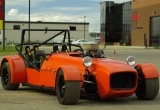
So here is the front suspension of my car.
Attachment:
IMG_0814.JPG
See how the coilover is laying down on the job? The coilover is out of a Caterham so I'm guessing that the spring rate is close to what I need. The suspension bottoms out when the coils compress to where they become a solid unit. Not a good thing. I'm going to use a 1.5" square tube to make a new mount that is further outboard and a bit higher. First off I measured the bolt to bolt length of the coilover with the car sitting on the floor. Then I made up a spring mockup that is the same length. Here it is with the uncompressed coilover.
Attachment:
IMG_0806.JPG
Then I had to clear the air cleaner and it's mount out of the way. That meant grinding off the brack...um mounting thingy. I think that means that I've now ground off and replaced just about every mounting thingy on the car.
Attachment:
IMG_0790.JPG
Attachment:
IMG_0807.JPG
The turbocharger something or other valve was also in the way so part of the induction piping had to come off as well.
Attachment:
IMG_0794.JPG


You do not have the required permissions to view the files attached to this post.

_________________
My car viewtopic.php?f=37&t=16434
1930s Style Sports Car viewtopic.php?f=36&t=16888


Top
 Profile  
Reply with quote  
PostPosted: February 13, 2016, 8:45 pm 
Offline
User avatar

Joined: June 12, 2012, 8:40 pm
Posts: 472
Location: Mount Airy, NC
Now that the way is clear, I can start fabbing up the new mount. Notice that the old upper mount is still in place just in case..
Attachment:
IMG_0809.JPG
Special high performance C clamps make welding unnecessary. Here is the car back on the floor with the new mount.
Attachment:
IMG_0815.JPG
I ran the tube across the frame to the other side to make the mount over there too. Notice that the coilover is now more upright.
Attachment:
IMG_0816.JPG
. Since the first NASCAR race of the year is coming on in a few minutes that is as far as I'll go tonight. Tomorrow, welding and more bracing then more welding.


You do not have the required permissions to view the files attached to this post.

_________________
My car viewtopic.php?f=37&t=16434
1930s Style Sports Car viewtopic.php?f=36&t=16888


Top
 Profile  
Reply with quote  
PostPosted: February 14, 2016, 2:52 am 
Offline
User avatar

Joined: July 29, 2006, 9:10 pm
Posts: 3164
Location: Oregon, usually
If you have another job that needs those C-clamps, you might want to consider using...mounting thingies, to hold the upper shock mount tube to your chassis. That way if you want to do shock angle adjustments, you can just fab another shock mount tube. That's how I did mine, and it was cheaper than replacing the springs.

_________________
Locost builder and adventurer, and founder (but no longer owner) of Kinetic Vehicles


Top
 Profile  
Reply with quote  
PostPosted: February 14, 2016, 9:57 am 
Offline
User avatar

Joined: September 22, 2005, 8:12 am
Posts: 1880
Location: 4AGE in S.E. Michigan
I know I would not be able to pull my engine /trans with that tube across those "V" support tubes. Do you have enough space to separate the engine from the tranny, then just pull the engine? Dave W


Top
 Profile  
Reply with quote  
PostPosted: February 14, 2016, 7:14 pm 
Offline
User avatar

Joined: August 27, 2005, 1:04 am
Posts: 1414
Location: Kamloops, BC, Canada
I did similar front shock mounts on my car, but I didn't run the 1.5" tube all the way across the frame. My shocks are still mounted pretty close to the tube though. The way I did it leaves lots of room to pull the engine.
Image
Kristian

_________________
V6 in a book frame build. Now registered.
viewtopic.php?f=35&t=7587
viewtopic.php?f=33&t=18172


Top
 Profile  
Reply with quote  
PostPosted: February 14, 2016, 7:38 pm 
Offline
Automotive Encyclopedia
User avatar

Joined: December 22, 2006, 2:05 pm
Posts: 8042
I like the old headlight bar adjusters. I guess you decided to move them forward?
Looks like bumpsteer is minimal too.
Can't see that PPF though!

_________________
Miata UBJ: ES-2074R('70s maz pickup)
Ford IFS viewtopic.php?f=5&t=13225&p=134742
Simple Spring select viewtopic.php?f=5&t=11815
LxWxHt
360LA 442E: 134.5x46x15
Lotus7:115x39x7.25
Tiger Avon:114x40x13.3-12.6
Champion/Book:114x42x11
Gibbs/Haynes:122x42x14
VoDou:113x44x14
McSorley 442:122x46x14
Collins 241:127x46x12


Top
 Profile  
Reply with quote  
PostPosted: February 14, 2016, 8:29 pm 
Offline

Joined: June 24, 2007, 6:04 pm
Posts: 1521
I did a bolt on cross bar tube that I could remove if I was taking the engine out, also handy for my over flow reservoir.
Extended my shocks out as well.

Al


You do not have the required permissions to view the files attached to this post.

_________________
Super Seven 3.4


Top
 Profile  
Reply with quote  
PostPosted: February 15, 2016, 9:36 am 
Offline
User avatar

Joined: June 12, 2012, 8:40 pm
Posts: 472
Location: Mount Airy, NC
I was all fired up on finishing yesterday. I welded in the cross bar but ran out of shielding gas before I was finished. Last night I checked here and saw the suggestions to bolt the bar in. That was a good idea but I'm well past that part now. I have 6 1/2" to move the engine forward to get it out so I'm thinking I'll be fine but If not I'll do like turbo_bird to get more room. The coilover is about as far out as I can get it so the only adjustment could be in. If I really feel I need to go in I'll have to do a little cutting on the tube to get the coilover moved in. Time will tell, but I think I'm ok.

While I had things apart I decided to measure the bump steer. I left the camera home so no pictures right now. I did bring the measurements in and I'll spend some time sorting them out to see where it stands. It looks waaaaay off. I've only got 350 miles on the car since it took me a while to sort out the fuel system and those miles are just around town. I haven't been above 50 yet but I have hit lots of bumps. This is Pennsylvania, land of awful roads. So far no bad behavior except for the bottoming of the coils. I'll report back when I have the numbers.
'

_________________
My car viewtopic.php?f=37&t=16434
1930s Style Sports Car viewtopic.php?f=36&t=16888


Top
 Profile  
Reply with quote  
PostPosted: February 17, 2016, 4:00 pm 
Offline
User avatar

Joined: June 12, 2012, 8:40 pm
Posts: 472
Location: Mount Airy, NC
Some pictures from the bump steer measurement. Laser level taped to the front disk.
Attachment:
IMG_0797.JPG
I taped a piece of posterboard to the workbench as a target.
Attachment:
IMG_0799.JPG
I lifted the suspension (without the coilover) through a range of travel, marking the laser location at intervals. I ran through it twice to make sure it was repeatable. Then I transferred the measurements to AutoCAD.
Attachment:
Bump Data.jpg
The numbers above are the raw data. The posterboard was 87.5" from the hub center. The wheels are 15". If I read the instructions on line correctly all I need to do is multiply 2.258" by 15"/87.5" which is .387" of bump steer. The way I've done this does not account for the whole assembly moving in towards the vehicle centerline but that would only make the toe out reading worse. The fancy setup I saw on the Longacre Racing web site and others accounted for this using a tool that moved with the hub.

Longacre Racing had the following words:

My recommendation is to run .005 to .015 thousands of bump out but never allow the tires to bump in. Excessive bump over .050 can slow your car down.

It would appear that I'm way out of the ballpark. So far out that I should be able to verify this with a tap measure on the disk tonight.


You do not have the required permissions to view the files attached to this post.

_________________
My car viewtopic.php?f=37&t=16434
1930s Style Sports Car viewtopic.php?f=36&t=16888


Top
 Profile  
Reply with quote  
PostPosted: February 17, 2016, 4:55 pm 
Offline
Mid-Engined Maniac

Joined: April 23, 2006, 8:26 pm
Posts: 6418
Location: SoCal
If I understand your test setup correctly, you're looking at the data wrong. If you project a light straight forward off the upright and move it through its range, it'll show "bumpsteer" even if it has none. That's because both the upper and lower A-arms move on arcs, so the combination guarantees that the upright will move inward in bump. Since your laser can't differentiate between moving parallel to its previous location, versus actually rotating, you're seeing a combination of the two. Said another way, if I project a laser dot on the wall and show it to you moving sideways, you can't tell whether I'm holding the laser steady and stepping sideways, or just rotating it.

IMHO, the only way to do it right is to make the board setup you see people using that has one dial indicator and a long screw. Any other setup confuses bumpsteer with A-arm arc.

_________________
Midlana book: Build this mid-engine Locost!, http://midlana.com/stuff/book/
Kimini book: Designing mid-engine cars using FWD drivetrains
Both available from https://www.lulu.com/


Top
 Profile  
Reply with quote  
PostPosted: February 17, 2016, 6:40 pm 
Offline
Automotive Encyclopedia
User avatar

Joined: December 22, 2006, 2:05 pm
Posts: 8042
"Put that thing away! You don't really want to hurt me do you?" -Capt. Kirk

Also, I took a look at Longacre's laser method. It takes two with two targets set up; one behind and one forward, noting the difference with suspension travel.

A large, hard back book or box with a hinged lid can indicate bumpsteer. How big is the box the laser came in?
Sorry, I could not resist. :cheers:

_________________
Miata UBJ: ES-2074R('70s maz pickup)
Ford IFS viewtopic.php?f=5&t=13225&p=134742
Simple Spring select viewtopic.php?f=5&t=11815
LxWxHt
360LA 442E: 134.5x46x15
Lotus7:115x39x7.25
Tiger Avon:114x40x13.3-12.6
Champion/Book:114x42x11
Gibbs/Haynes:122x42x14
VoDou:113x44x14
McSorley 442:122x46x14
Collins 241:127x46x12


Top
 Profile  
Reply with quote  
PostPosted: February 18, 2016, 9:50 am 
Offline
User avatar

Joined: June 12, 2012, 8:40 pm
Posts: 472
Location: Mount Airy, NC
KB58 wrote:
If you project a light straight forward off the upright and move it through its range, it'll show "bumpsteer" even if it has none. That's because both the upper and lower A-arms move on arcs, so the combination guarantees that the upright will move inward in bump.


Yup, mentioned that in a previous post. Since the assembly moves in towards the centerline of the car and the readings still moved out I think that shows toe out. I tried again last night, this time with a tape measure. I set the suspension at ride height and measured from the top of the backing shield (it prevented me from measuring directly on the disc) on one side top the same spot on the opposite side. Then I measured from the furthest forward part of the backing shield (roughly level with the disc center) to the same spot on the opposite side. I raised the suspension 2" and repeated the measurements. This showed that the distance between the tops moved in 3/4". The distance between the front points moved in 9/16". I couldn't get the tape on the lowest part of the backing shield. I'll try something else tonight. Using just the numbers I had, ratioing them out from the disc diameter to the wheel diameter, I get .256" of toe out. This number will get smaller once I account for the movement at the bottom of the disc.

Miatav8,MstrASE,A&P,F wrote:
"Put that thing away! You don't really want to hurt me do you?" -Capt. Kirk


Aye captain!

_________________
My car viewtopic.php?f=37&t=16434
1930s Style Sports Car viewtopic.php?f=36&t=16888


Top
 Profile  
Reply with quote  
PostPosted: February 18, 2016, 10:15 am 
Offline

Joined: May 1, 2012, 9:43 am
Posts: 336
Location: Sidney, BC, Canada
You can still use the laser method the way you did it with a single laser, you just have to subtract the inboard movement of the A arm. The horizontal movement can be easily calculated from your suspension geometry - you just need the length of your A arms and starting and ending angle. If you put your laser in line with the upper or lower A arm then you can just use the travel of that arm for the calculations; if it's somewhere between the two then you have to interpolate. The rotation of the laser will be exaggerated due to the distance to the wall, but the lateral movement of the hub won't be so it's just a direct subtraction.


Top
 Profile  
Reply with quote  
PostPosted: February 18, 2016, 10:25 am 
Offline
User avatar

Joined: June 12, 2012, 8:40 pm
Posts: 472
Location: Mount Airy, NC
I also need to go back and watch the episode of Project Binky where Nik does his bump steer. I think he did the laser on the wall thing. I can get my tank of shielding gas filled tomorrow so I will be back to finishing up the welding, then on to painting and reassembly. Too bad the township has dumped so much salt on the roads, there won't be any test drives this weekend.

_________________
My car viewtopic.php?f=37&t=16434
1930s Style Sports Car viewtopic.php?f=36&t=16888


Top
 Profile  
Reply with quote  
PostPosted: February 18, 2016, 10:53 am 
Offline
Mid-Engined Maniac

Joined: April 23, 2006, 8:26 pm
Posts: 6418
Location: SoCal
Well something's wrong somewhere. With that much bump steer, you would have driven off the road into a ditch - with soiled shorts, or you're somehow completely numb to spectacularly-bad bump steer (~3"?!!). Neither fits the situation, so I vote that you're better than that and it's just a measurement thing. The front view of your suspension and steering arms doesn't look all that terrible (though the rack attachment point does appear to be too far inboard), but your results describe a situation that's much worse.

Image

_________________
Midlana book: Build this mid-engine Locost!, http://midlana.com/stuff/book/
Kimini book: Designing mid-engine cars using FWD drivetrains
Both available from https://www.lulu.com/


Top
 Profile  
Reply with quote  
Display posts from previous:  Sort by  
Post new topic Reply to topic  [ 29 posts ]  Go to page 1, 2  Next

All times are UTC - 5 hours [ DST ]


Who is online

Users browsing this forum: Google [Bot] and 9 guests


You cannot post new topics in this forum
You cannot reply to topics in this forum
You cannot edit your posts in this forum
You cannot delete your posts in this forum
You cannot post attachments in this forum

Jump to:  
cron
POWERED_BY