LocostUSA.com

Learning how to build Lotus Seven replicas...together!
It is currently April 19, 2024, 1:27 am

All times are UTC - 5 hours [ DST ]


Post new topic Reply to topic  [ 29 posts ]  Go to page 1, 2  Next
Author Message
PostPosted: December 13, 2017, 1:48 am 
Offline
User avatar

Joined: July 6, 2008, 12:48 am
Posts: 653
Location: Amador County, CA
Hey guys, I'm wondering if it's possible to put together a list of "rules of thumb" or directions for building front suspension. Basically something like, "without modelling or math just do these things and the car should be road driveable and relatively safe."

So far this is what I have...
-Setup frame at desired ride height.
-Build a jig for the uprights that is...
...equal to or wider than rear
...about 1 degree of camber
...6-8 degrees of caster
-Set up lower control arms to be level between the pivot and the ball joint.
-Set up upper control arms to be angled toward the car. About how many degrees? Is there a ratio of control arm length that is typical on these cars?
-Make sure that control arm pivots lines are parallel with the center line of the chassis. I think this is not necessary for all suspensions but in order to keep it simple and predictable they should be?

For steering... Please correct me here, I haven't looked at many steering setups yet...
At ride height and pointed straight the tie rod pivots should intersect the plane between the control arm pivot lines on their respective sides.
Rack should be as in line with the tie rod ends as possible. Not sure if this is true? What is the trade off when not in line?
Make sure tie rods don't hit anything, steering lock to lock, cycling suspension fully.

What am I missing? Is this dumb? Do I just need to buy books and read?

I'll try edit this post later and add whatever conclusion I come to.

_________________
+442 - Miata


Top
 Profile  
Reply with quote  
PostPosted: December 13, 2017, 3:08 am 
Offline
The voice of reason
User avatar

Joined: January 10, 2008, 4:47 pm
Posts: 7652
Location: Massachusetts
Hi Toylocost, nice to see you post again. You've done a good job of summarizing the approach. It's late so I won't write a lot but will give two details.

If you don't have the inboard pivots of the wishbones parallel to the centerline of the car it makes the spindle motion more complicated. If the spindle moves forward and backwards going up or down, that means you have anti-dive or pro-dive built in. It could also affect other things but it's not really a disaster or anything. The original sevens had some of this if I remember right. You can also get the forward and backwards motion by tilting the wishbones.

If the steering arms reach forwards or backwards that affects or gives you Ackermann. For a front steer spindle you want the arms reaching forward a bit as the go outwards. You described choosing the length of the steering arms very well. They should also have an angle that is proportional to the wishbones. So if the arm is the same height as the upper wishbone it should be at the same angle and if it's same height as the lower wishbone it should be the same angle as the lower wishbone.

_________________
Marcus Barrow - Car9 an open design community supported sports car for home builders!
SketchUp collection for LocostUSA: "Dream it, Build it, Drive it!"
Car9 Roadster information - models, drawings, resources etc.


Top
 Profile  
Reply with quote  
PostPosted: December 13, 2017, 11:37 am 
Offline
User avatar

Joined: September 30, 2005, 1:28 am
Posts: 1330
Location: Sunny-Okanagan, Canada, eh?!
If the upper control arm is angled down dramatically, you get a short swing arm length, which can give a fairly aggressive camber curve. It may also make the roll center move around (I have to look it up). I am not convinced I'd notice.

I DO know that you are going to want a LOW front roll center on these cars, to make the front stick. Shoot for ground level. This can be done if the upper and lower arms are parallel, but that takes away from a decent camber curve. Parallel with a SHORT upper arm can give you a reasonable roll center location and camber curve, but the roll center will move more. Packaging will likely dictate what has to work.

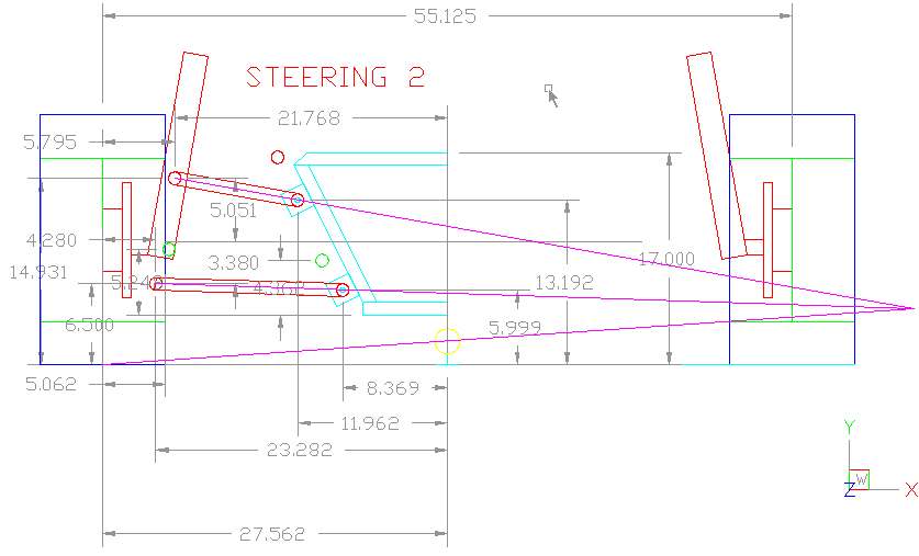
To determine the roll center, draw your spindle, tire, and control arms in their locations, and draw a line through their centers off to the distance. Where the upper arm centerline meets the lower arm centerline is your instant center. Draw a line from there back to the centerline of the wheel. Where ~that~ line crosses the center of the vehicle is your roll center.

DON'T COPY THIS DESIGN; I wouldn't do it this way again:
Image

The green circles above are where the inner and out tie rods are. Draw a line from the outer tie rod to the instant center - that's where the inner tie rod needs to sit vertically. Whatever the ratio is for the tie rod location on the spindle (between the ball joints), figure out the same ratio to locate the inner tie rod between the inner control arm pivots. This will minimize bump-steer.

Some rules-of-thumb are having the upper arm 2/3 the length of the lower.

Keep the lower arms parallel (ball-joint to inner-pivot) to the ground.

Keep the upper and lower arms parallel to each other and to the ground as viewed from the side - it makes dealing with bump steer easier, and you don't really need anti/pro-dive in a car this light.

_________________
The Lethal Locost
The Lethal Locost 2 - Even More Lethalerer


Last edited by SkinnyG on December 13, 2017, 6:36 pm, edited 1 time in total.

Top
 Profile  
Reply with quote  
PostPosted: December 13, 2017, 12:36 pm 
Offline
The voice of reason
User avatar

Joined: January 10, 2008, 4:47 pm
Posts: 7652
Location: Massachusetts
SkinnyG that's a good writeup and diagram. Can you just say what you didn't like about that setup? Too much downangle on the upper arm?

Try for less than 10 degrees down angle on the upper arm.

One practical detail is that you will not be able to choose where the outer tie-rod pivot is, it's fixed by the steering arm on your spindle. On the Pinto spindle I'm looking at it is maybe 1" outboard of the plane between the upper and lower ball joint. This not a problem, your description and the diagram from SkinnyG with the little green circles show you the length and angle you need for that tie-rod. It is OK for the whole tie-rod to be one inch outboard of where the green circles are. It's motion comes from the length between pivots and the angle which are figured from the drawing.

In real life you can probably clamp some yardsticks or stock to the frame and eyeball the length and angle. You will have to set the height of the rack to make the inner pivot be the correct position to provide the length you want.

I noticed recently that the Pinto racks are about 24.5" but the Fox Mustang racks are closer to 21", if that helps you out. Double check before you buy something.

_________________
Marcus Barrow - Car9 an open design community supported sports car for home builders!
SketchUp collection for LocostUSA: "Dream it, Build it, Drive it!"
Car9 Roadster information - models, drawings, resources etc.


Top
 Profile  
Reply with quote  
PostPosted: December 13, 2017, 5:24 pm 
Offline
User avatar

Joined: July 4, 2006, 5:40 pm
Posts: 1994
Location: Novato, CA
I built my suspension with no math, and my car handles like magic. The frame and spindles are going to determine almost everything. The only rule of thumb is to keep your lower A-arms parallel to the ground at static height. The only variable is the angle of the upper A-arms. 10 degrees is a good rule of thumb for that.

With the lower A-arm attached to the frame pickups and parallel to the ground, attach the spindle at the proper angle (-1 degree camber is a good place to start, but it should be adjustable anyway; I used the Book caster of 5.3 degrees), and that determines the outboard position of the upper A-arm. Angle the upper A-arm down to give you a reasonable roll center (9 degrees in my case), and that determines a) the location of the upper A-arm pickups on the frame and b) the length of the upper A-arms. That's all there is to it. Of course it's easier if you draw it up first.


Top
 Profile  
Reply with quote  
PostPosted: December 13, 2017, 6:06 pm 
Offline
User avatar

Joined: January 2, 2009, 1:45 pm
Posts: 1322
Location: Halifax, Nova Scotia
And to make life simpler, after mocking up, adjust the track to make a rack the right length without cutting. I used Staniforth's string computer: after my first iteration I found the closest stock rack and then adjusted track to suit and did a final check. Actually I lie: after my first iteration I realized my selected tires were too tall to get reasonable roll centre and bought new tires. THEN, I iterated again, before adjusting track to fit the 'closest' rack (and MGB in my case). Never a calculation in sight - just cardboard, sticks, string and pins.

_________________
Warren
Isuzu Pickup/SR20DE, +401 COLD frame
Build Log: viewtopic.php?f=35&t=11601


Top
 Profile  
Reply with quote  
PostPosted: December 13, 2017, 6:47 pm 
Offline
User avatar

Joined: September 30, 2005, 1:28 am
Posts: 1330
Location: Sunny-Okanagan, Canada, eh?!
That suspension design was what I came up with when I was using the shortened struts of the Corolla GTS way back in about 2005-ish.

Shortened struts wouldn't pass inspection, so I modified everything to use Chevette spindles, just eye-balling what would "look" right (no math).

After the inspection I shortened a Triumph rack to get rid of bump-steer.

Then through two years of street and LOTS of autocross use to sort out the handling, that roll center turned out to be way too high - to get the roll center DOWN and to get the front of the car to grip, I had to lower the car so much that I now have very little ground clearance (but the roll center is ON the ground now). I also still have to run fairly aggressive static camber (-2.5°) for good tire wear (at autocross, I don't care about tire wear on the street). I think a shorter and less angled upper arm would help this, and maybe a bit more caster to compensate.

I also happen to run a very LOW rear roll center (which I believe in), but others have suggested that my low rear roll center is why the car understeered so much - they suggest raising the rear roll center - but higher roll centers induce jacking, which I don't want (I don't want to unload the inside rear tire on a corner).

_________________
The Lethal Locost
The Lethal Locost 2 - Even More Lethalerer


Top
 Profile  
Reply with quote  
PostPosted: December 13, 2017, 9:19 pm 
Offline
User avatar

Joined: July 17, 2008, 9:11 am
Posts: 6415
Location: West Chicago,IL
So somebody really smart, answer me.

Quote:
Peter Venkman: Ray, pretend for a moment that I don't know anything about metallurgy, engineering, or physics, and just tell me what the Hell is going on.


How much does roll center really matter if the springs are really stiff and or one uses stiff sway bars? As I see it, as the suspension travels less, the desired effects are less so the "ideal geometry" has less impact. How does one calculate the roll center of car with a solid bar replacing the springs? Even Colin Chapman said... oh wait. His quote is in my tag line. :mrgreen:

_________________
Chuck.

“Any suspension will work if you don’t let it.” - Colin Chapman

Visit my ongoing MGB Rustoration log: over HERE

Or my Wankel powered Locost log : over HERE

And don't forget my Cushman Truckster resto Locostusa.com/forums/viewtopic.php?f=36&t=17766


Top
 Profile  
Reply with quote  
PostPosted: December 13, 2017, 9:54 pm 
Offline
Mid-Engined Maniac

Joined: April 23, 2006, 8:26 pm
Posts: 6419
Location: SoCal
Consider where the roll center is when you're cornering with hardly any weight on the inside tire... That's why I switched to the force-based method and never looked back.

_________________
Midlana book: Build this mid-engine Locost!, http://midlana.com/stuff/book/
Kimini book: Designing mid-engine cars using FWD drivetrains
Both available from https://www.lulu.com/


Top
 Profile  
Reply with quote  
PostPosted: December 13, 2017, 11:08 pm 
Offline
User avatar

Joined: June 8, 2010, 8:02 pm
Posts: 621
Location: White Rock, BC, Canada
When it comes to suspension geometry and the average Locost type car, I'm all for getting it built and worry about the details later (having done the opposite on my car and regretting it). Much of the thought that goes into suspension design will not be noticed by the average driver.

I would suggest looking at it from a different angle: Instead of thinking about what will make it handle well, make a list of the things that we know will make it handle badly. Bumpsteer, Bind, lack of wheel-travel and Jacking are what come first to my sleepy mind (anyone else have more to add?). So long as you avoid that list of things, the rest is manageable with basic knowledge/adjustments. The typical Locost and Locoster is not going to notice if the car could use a little more anti-dive etc, but he is going to notice the instability that Bumpsteer etc cause.

Cheers.

_________________
Build log: viewtopic.php?t=9291


Top
 Profile  
Reply with quote  
PostPosted: December 13, 2017, 11:39 pm 
Offline
User avatar

Joined: December 17, 2010, 1:24 pm
Posts: 1580
Location: Gainesville, Mo.
KB58 wrote:
That's why I switched to the force-based method and never looked back.


Kurt, could you expound a bit on "the force-based method"? I've heard the term used here occasionally, but have no idea what it is.

_________________
Mike - Read my story at http://twinlakesseven.blogspot.com/


Top
 Profile  
Reply with quote  
PostPosted: December 14, 2017, 12:20 am 
Offline
The voice of reason
User avatar

Joined: January 10, 2008, 4:47 pm
Posts: 7652
Location: Massachusetts
I'm not exactly sure if this is what Kurt is saying, but what I look at is the angle of the lower red ( magenta? ) line in SKinnyG's drawing. It's the line from the contact patch to the instant center. That line shows the angle that the suspension is resisting the force of cornering. If the wheel on the other side has just lifted it is completely accurate. I don't bother with the inner wheel, for the most part.

If you pushed on a rod against the wall at that angle you can imagine some of your force is lifting your hand. So you want that to be a small angle, maybe under 4 degrees if you can do it. If you have a solid rear axle you probably can't but 10 degrees is a lot. So you do what you can.

If we knew the height of the roll center in SkinnyG's diagram and the track we could calculate the percentage of jacking. With a 2" Rc and 30" to the contact patch it might indicate maybe possibly something like 50 lbs. of jacking? Just a wild guess.

Quote:
How much does roll center really matter if the springs are really stiff and or one uses stiff sway bars?


It still matters. Roll centers are geometric resistance to roll. Springs and anti roll bars are elastic resistance to roll. Together they give your answer. If the roll center is as high as your center of gravity it doesn't matter how stiff your springs are, all the stiffness is provided by the roll center. Confusing huh!? :rofl:

_________________
Marcus Barrow - Car9 an open design community supported sports car for home builders!
SketchUp collection for LocostUSA: "Dream it, Build it, Drive it!"
Car9 Roadster information - models, drawings, resources etc.


Top
 Profile  
Reply with quote  
PostPosted: December 14, 2017, 2:03 am 
Offline
User avatar

Joined: July 6, 2008, 12:48 am
Posts: 653
Location: Amador County, CA
Thanks for the discussion guys, it's helping a lot. I'm confident enough to move forward now without worry.

Things I will add to the original list...
-Tie rod angle in relation to control arms and instant center
-UCA at 2/3 the length of the LCA could be a loose rule of thumb
-Keep all control arms level front to back
-10 degrees or less down angle on UCA

More questions that I have now...
What is an accaptable range for roll center? Seems that I need to have a fairly low angle on the UCA to get the RC near the ground but I can't shorten the UCA either so may get positive camber in a corner if it rolls far enough.
How much body roll would you think is average?

nick47 says that 10 degree on UCA is a good rule of thumb, If I put my UCA at 10 degrees right now my RC would be higher than ride height. It's looking like I will be at 3-5 degrees on the UCA with a RC of 1-3 inches. I don't want to post my full numbers because I don't want this thread to turn into something that is specific to my situation.

Maybe a better rule of thumb is a range of acceptable roll centers and a typical body roll value where you would aim to be in the roll center range but also still be near 0 camber at full roll? Or is body roll too dependent on other factors?

_________________
+442 - Miata


Top
 Profile  
Reply with quote  
PostPosted: December 14, 2017, 8:34 am 
Offline
User avatar

Joined: September 22, 2005, 8:12 am
Posts: 1880
Location: 4AGE in S.E. Michigan
U/C/A design at lower angles mean that what ever roll the vehicle will experience the camber is almost at a 1 to 1 ratio relative to the same degree of change in tire camber. The only option is to run higher static neg camber. Higher arm angle would mean less roll effect plus easier to get a lower roll center. DaveW


Top
 Profile  
Reply with quote  
PostPosted: December 14, 2017, 11:12 am 
Offline
User avatar

Joined: September 30, 2005, 1:28 am
Posts: 1330
Location: Sunny-Okanagan, Canada, eh?!
Both an angled upper arm, AND a shorter upper arm contribute to camber curve. But good camber curve and good roll center and long swing arm length can be fun to chase.

Was reading through my references, and someone from Ford Engineering said if you are running very low roll centers, you don't need to worry about roll center migration because it's not really an issue at that point.

_________________
The Lethal Locost
The Lethal Locost 2 - Even More Lethalerer


Top
 Profile  
Reply with quote  
Display posts from previous:  Sort by  
Post new topic Reply to topic  [ 29 posts ]  Go to page 1, 2  Next

All times are UTC - 5 hours [ DST ]


Who is online

Users browsing this forum: No registered users and 7 guests


You cannot post new topics in this forum
You cannot reply to topics in this forum
You cannot edit your posts in this forum
You cannot delete your posts in this forum
You cannot post attachments in this forum

Jump to:  
POWERED_BY