LocostUSA.com
http://locostusa.com/forums/

A arm dimensions/diagrams for s10 knuckles and book frame
http://locostusa.com/forums/viewtopic.php?f=5&t=209
Page 4 of 5

Author:  KB58 [ September 15, 2006, 2:42 pm ]
Post subject: 

In the picture above, it looks like only the upper corner of the top shock bracket is welded to the car. True or not? If so it really needs to be corrected, otherwise it can bend, rotating upward and potentially breaking off.

Author:  chetcpo [ September 15, 2006, 4:07 pm ]
Post subject:  Re: Brakes?

KENLUDE97 wrote:
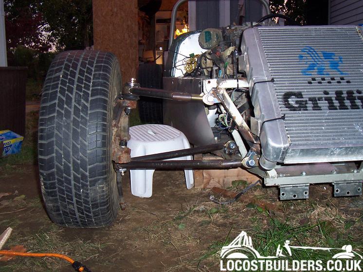
Now with using the S10 spindles does this hold you to using only s10 parts? Or are there other GM brake components? Such as a "racing" brake pad. What does everyone use?


I just looked on www.tirerack.com for a quick reference on Brakes and it seams like hawk makes a HP+ for the S10! :shock: I'm shocked! But would this be enough pad for straight track use? The car would be used as a Toy and occisional racer, and weekely Auto-xer.


Thanks
Ken

I'm pretty sure that's all the pad you need, if not more. You may have trouble getting it up to temp in a little lightweight locost when the pad is made for a vehicle that ways more than twice as much.

Author:  KENLUDE97 [ September 15, 2006, 7:30 pm ]
Post subject: 

Yea i thought about that.... hummm Ok i think that i will start with that.


Thanks. :D

Author:  KENLUDE97 [ September 18, 2006, 12:55 pm ]
Post subject: 

I drew "derf's" a-arms. And now i need to know where they mate to the chassis. Does the "front" stay in the same places and the "rear" mounts just move back?

And are they located at the same height as the book?

And when i use a 5/8" Rod end they interfear with the brakets? Did you make new brackets?
Image

thanks
Ken

Author:  chetcpo [ September 18, 2006, 4:55 pm ]
Post subject: 

I'm not sure, here is a pic of them installed.

Image

Author:  KENLUDE97 [ September 18, 2006, 7:09 pm ]
Post subject: 

OH THAT IS A HUGE HELP!

Thanks for the pic! I have the bottom mount all the down at the bottom, and moving it up solves most of my issue.

Author:  sagz [ November 1, 2006, 6:13 pm ]
Post subject: 

is there any reason why I couldn't make a set of arms like this:
the dimensions match derfs drawings. just curious.
Image

Author:  GatoEnFuego [ November 1, 2006, 6:52 pm ]
Post subject: 

bending thick wall DOM isn't easy and could possibly compromise it's strength (not sure how likely that is). I can see bending one side of the upper to clear the shock but bending them all like that would be a lot of work and possibly not as safe. but i'm no expert, i just play one on the intraweb.

Author:  sagz [ November 1, 2006, 6:59 pm ]
Post subject: 

even though this way I'm reducing the number of welds?

Author:  chetcpo [ November 1, 2006, 8:28 pm ]
Post subject: 

sagz wrote:
even though this way I'm reducing the number of welds?


You'll still need to put some bracing in there but if you can actually bend them like that I don't see why they wouldn't work.

Author:  GatoEnFuego [ November 1, 2006, 11:40 pm ]
Post subject: 

sagz wrote:
even though this way I'm reducing the number of welds?


just use straight tube and tilt the mounting brackets inwards.

Author:  TorontoLocost [ November 23, 2006, 9:05 pm ]
Post subject: 

Hi


Thanks for the drawing. I like to know what is the production year of the S10 and engine size?

Thanks
Leo

Author:  squarefour [ October 2, 2007, 6:14 pm ]
Post subject:  threaded tubes for Datz510

Almost 2 years too late, but here's another option for threaded tubes:
http://www.speedwaymotors.com/p/3305,32 ... Plain.html
(Speedway Motors TIE ROD/DRAG LINK KIT)

Comes out to about $27 per end, but comes with a rod end. Also, 7/8" OD, so possibly less heavy duty than the 4x4 sourced parts.

Author:  rayjay [ June 23, 2009, 5:28 pm ]
Post subject:  Re:

KB58 wrote:
In the picture above, it looks like only the upper corner of the top shock bracket is welded to the car. True or not? If so it really needs to be corrected, otherwise it can bend, rotating upward and potentially breaking off.


I think the frame tabs for the control arm pivots look pretty thin too.

Author:  conceptzrqt [ March 15, 2010, 8:35 am ]
Post subject:  Re: A arm dimensions/diagrams for s10 knuckles and book frame

If I may,
Did you take into thought when using heims on the inside of the arms that if and when adjusted the distance from center of one heim to the other would get wider or narrower? IE you cant weld an a-arm solid, you need to have an adjustable trailing arm or a way to add shims at the chassis mounting point.

I say this because when I built my first reverse trike I did the same thing as you are doing here. I welded all of my ends and when I went to adjust them they expanded to an uncomfortable point and made it hard to get the heims set into place. My thought on this was to weld up one side of the arm and make the other side bolt on so that it would be adjustable, using a clevis (I think that is what they call it) the trailing arm would now be adjustable.

Also, the shock mounts at the chassis I had thought was a good idea but looking back at it I think they should have been boxed in a little on the top and bottom to make them a little stronger. I am not saying don’t use these but I think they should be a little stronger…some of mine might have been deformed a little. But any deforming could have been from the fact that when I adjusted the arms it put unneeded tension on the inside or outside of the mount…or both.

I am not sure I explained myself very well. If I need to I can draw up or edit some pics of what I am trying to say I will. Let me know if needed or interested.

Thank you.

Page 4 of 5 All times are UTC - 5 hours [ DST ]
Powered by phpBB® Forum Software © phpBB Group
https://www.phpbb.com/