So I'm starting to work on designing my car and I have a few ideas, both concrete and abstract to work out. Awhile ago I posted a topic about a
possible solution to an AWD setup, but due to lack of parts availability and after taking apart a FWD transaxle I've come up with a different design. I haven't started picking up parts yet because I want to have a good amount of the design done before I start gathering too many parts, and I'm also fairly broke at the moment (still in school and working part time). So at this point my locost is purely in the design phase. Given that I plan to work on learning SolidWorks since I got a student copy from a friend a few years ago and start modeling out the frame. I'll be using the VSusp website for most of the suspension geometry then translating that into Solidworks.
Now on to the actual Ideas part:
Drive train:
2.8VR6 engine from a VW GTI/Jetta/GLI/Passat/where ever I can get it.
Quicktime Bell housing from Jegs
Tremec T5 from a mid-'90s Mustang
Custom Transfer case using FWD transaxle R&P gears and Diff (more on that later)
Ford 8.8 IRS diffs front and rear, Auburn Ected in the rear
215/45R17 Tire size
Suspension
SLA all 4 corners
Full custom (control arms and Uprights)
Enough Camber gain to eliminate Track width change due to bump
Ackerman Steering
Roll center at least within the chassis
Rear roll center higher than Front
around .5" scrub radius
Caster, Camber, and Toe adjustments all independent hopefully using eccentrics
Frame:
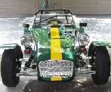
Keep the Lotus look with body work on
Probably around 6-12" of stretch (mostly for the Transfer case behind the seats)
A couple of inches extra height
Integrated roll cage
space for 2
Engine slightly offset to the right
overall weight of around 1500-1700 lbs
I'll be putting the drive train together first, and then stretching it out to fit the passengers with the transmission down the middle and the transfer case behind the seats. The transfer case will take input on the right side and put it through a ring gear from a FWD transaxle to a pinion from the same transaxle and into another ring gear which sends power to the front and rear diffs via a Torque biasing center diff (probably a Peloquin brand). It will be mounted directly in front of and possibly with the outdrive directly attached to the pinion shaft of the rear diff. Once the drive train is modeled I will add the suspension since the width of the frame will be determined by the width of the Diffs and where the axle CVs are. I'm thinking of using Thrust rated Heim joints (1765lbs thrust load) instead of ball joints and Rubber or Poly bushings for the frame side. After the drivetrain and suspension have been worked out I'll build the frame around everything.
So, what do you guys think? I know I'm probably being over ambitious but I can't help it I'm 23, and I won't get too much help while it's all theories, but any input would be greatly appreciated. I also need to get CAD models of the various drive train components so I can start mocking things up, does anyone have a good source for these? I'll have to read through all the Car9 stuff and start to work on the Tutorials for SolidWorks. I'm shooting for a budget of around 10K and a lot of trips to junkyards for parts, and I'll probably be adding in more after the car is built but that's normal.