LocostUSA.com

Learning how to build Lotus Seven replicas...together!
It is currently April 25, 2024, 4:49 pm

All times are UTC - 5 hours [ DST ]


Post new topic Reply to topic  [ 159 posts ]  Go to page Previous  1 ... 6, 7, 8, 9, 10, 11  Next
Author Message
PostPosted: February 6, 2014, 6:27 pm 
Offline

Joined: November 11, 2013, 2:11 pm
Posts: 97
Location: Frankfort, KY(for now)
Build and now! No discussion just build it


Top
 Profile  
Reply with quote  
PostPosted: February 6, 2014, 10:14 pm 
Offline
User avatar

Joined: November 12, 2008, 6:29 am
Posts: 3567
That's coming along awesome'ly Stephan, I likey!


Top
 Profile  
Reply with quote  
PostPosted: February 7, 2014, 12:31 am 
Offline
User avatar

Joined: July 27, 2013, 3:16 pm
Posts: 336
Location: Cedar City UT
thanks for the comments :wink:

i`m still pushing things around an inch here and there :? ...

i shortened the WB to 84 inches and dont see anything wrong with it ;

Image
high res; http://www.supermotors.net/getfile/1010789/original/ar4.jpg

there is still room behind the seat (for the battery ... and i dont want to sit too far back between the tires)
the distance from the engine side cover to the lower back edge of the seat is a little over 50 inches


however, i failed miserably at building the header :ack: ... that one will be thrown onto the (digital) scrap pile tomorrow :P

btw
rims are 16 x 6.5 with 205/55 tires

_________________
- Stephan - Image


Top
 Profile  
Reply with quote  
PostPosted: February 7, 2014, 12:33 am 
Offline

Joined: November 11, 2013, 2:11 pm
Posts: 97
Location: Frankfort, KY(for now)
How come you don't use a drivetrain setup like a slingshot dragster; you will be sitting on top of the axle though.


Top
 Profile  
Reply with quote  
PostPosted: February 7, 2014, 1:29 am 
Offline

Joined: August 12, 2012, 6:38 pm
Posts: 1937
Location: worcester county, Massachsetts
RB, the exhaust should exit down the side it exits the engine. No point in heating up your feet/legs, or the driveshaft unneccesarily

_________________
The B-3 build log: http://www.locostusa.com/forums/viewtopic.php?f=36&t=13941 unfortunately, all the pictures were lost in the massive server crash

The beginnings of the Jag Special,
https://www.locostusa.com/forums/viewtopic.php?f=36&t=19012
Again, all pictures were lost.


Top
 Profile  
Reply with quote  
PostPosted: February 7, 2014, 7:14 am 
Offline
User avatar

Joined: November 12, 2008, 6:29 am
Posts: 3567
robbovius wrote:
RB, the exhaust should exit down the side it exits the engine. No point in heating up your feet/legs, or the driveshaft unneccesarily


I would keep it as it is but go around the front of the engine first.


Top
 Profile  
Reply with quote  
PostPosted: February 7, 2014, 5:03 pm 
Offline
User avatar

Joined: July 27, 2013, 3:16 pm
Posts: 336
Location: Cedar City UT
jazz2561 wrote:
How come you don't use a drivetrain setup like a slingshot dragster; you will be sitting on top of the axle though.


sitting on top of the axle will not work for me;
my goal is to have a fairly high ground clearance with a very low center of gravity :wink:

robbovius wrote:
RB, the exhaust should exit down the side it exits the engine. No point in heating up your feet/legs, or the driveshaft unneccesarily

good point
this is how it was usually done at cars of that vintage (like on this Alfa P3)...
Image
... but i personally dont really like the look of an exposed exhaust system (imho it makes the sleek body look cluttered)
protecting bystanders (and my doggies & myself) from burns is also very important to me.

cheapracer wrote:
I would keep it as it is but go around the front of the engine first.


that could work ...
but unfortunately the clutch/trans is hanging fairly low over on that side of the engine
and the exhaust has also to compete with the sway bar for space

i think i just have to live with the heat (and spend a little extra for heat shielding and possible exhaust ceramic coating)

btw
i drove my "Muggy" (front engine Mustang V8 powered Dunebuggy) for years with the muffler right under the aluminum seat :shock:
... so i guess i`m used to feeling a little heat :P

_________________
- Stephan - Image


Top
 Profile  
Reply with quote  
PostPosted: February 8, 2014, 11:40 pm 
Offline

Joined: June 15, 2009, 10:52 pm
Posts: 142
Location: RTP, NC
Your design reminds me of the 1960 Lola Mk2...

Image

Image

http://www.theroaringseason.com/showthr ... a67e99a047

bryan


Top
 Profile  
Reply with quote  
PostPosted: February 9, 2014, 12:42 am 
Offline
User avatar

Joined: July 27, 2013, 3:16 pm
Posts: 336
Location: Cedar City UT
Brian

thank you for the pics and link :wink:

that frame is very interesting !

i just started drawing the main framework so i can use inspiration like that 8)

_________________
- Stephan - Image


Top
 Profile  
Reply with quote  
PostPosted: February 10, 2014, 9:07 pm 
Offline
User avatar

Joined: July 27, 2013, 3:16 pm
Posts: 336
Location: Cedar City UT
the frame is slowly taking shape;

Image
for a higher resolution click here; http://www.supermotors.net/getfile/1011078/original/ar5.jpg

i decided to base my frame on 4 main tubes that are bend to a large radius of 10 feet on a bender that i will build from scratch.

to compensate for the "weakness" of the large radius i will use 1.75" x .095" DOM for that.
if you look closely you will notice that the upper tubes step down to 1.5" forward of the firewall;
the idea is to make the cockpit "tub" the strongest point of the car (and it keeps the pieces UPS ship-able)

obviously i`m still missing a lot of tubing ... i`m still undecided on the shape of the rollbar/cage structure :?

i`m also still working on the (laser cut) front bulkheads that will give me precise LCA, UCA,
steering rack and shock mounting tabs as well as locate the main tubes.

most of the upright tubing is .75" x 1.5" x .065 " rectangular tubing to give me a flat tube for riveting the skin on,
as well as side impact protection without adding too much weight.

... i`m not exactly happy with the fuel tank ... its only 6 gallons ... maybe i will find a better solution :|

_________________
- Stephan - Image


Last edited by RoosterBooster on February 11, 2014, 1:00 am, edited 1 time in total.

Top
 Profile  
Reply with quote  
PostPosted: February 10, 2014, 9:19 pm 
Offline
User avatar

Joined: January 2, 2009, 1:45 pm
Posts: 1322
Location: Halifax, Nova Scotia
Why are you worried about 'weakness' of bent tubes? Yes, the bend introduces eccentricity that may be expected to reduce critical buckling loads, but with the tubes within a truss structure there should be enough redundancy and end constraints to overcome that concern. It is not even obvious that static load performance of the bent main tubes would vary greatly, if at all, from straight segments. I have dim memories of reducing analysis of arches to elemental straight bars in first year statics ...

But enough of that quibbling: I like what you are planning!

_________________
Warren
Isuzu Pickup/SR20DE, +401 COLD frame
Build Log: viewtopic.php?f=35&t=11601


Top
 Profile  
Reply with quote  
PostPosted: February 10, 2014, 10:18 pm 
Offline

Joined: January 31, 2008, 5:34 pm
Posts: 781
Location: SW Wes Consin
Might I suggest? Put a diagonal tube in your rear bay to make a pyramidal tail which will double your stiffness. Also IMHO your tubes are way over sized. This is simple enough to build a quicky with tubes of half the section. Then test it. Most locostts have way too much beam strength and not enough torsional resistance. Roll bars and intrusion guards are another story and really hard to integrate without a tin top or KB58 type of car. Lead on! Looking good!


Top
 Profile  
Reply with quote  
PostPosted: February 11, 2014, 12:47 am 
Offline
User avatar

Joined: July 27, 2013, 3:16 pm
Posts: 336
Location: Cedar City UT
Warren, vroom; thanks for your thoughts :wink: ....i appreciate it :cheers:

Warren
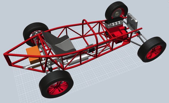
over the years i learned to look at every bend as a weakness (under very high load),
and my cars evolved to a almost "zero bend" structure.
like this mid-ship engine "Truggy" that i called V-Rex (for velocity rex due to its massive HP/torque engine):

http://www.supermotors.net/getfile/779727/original/dscf1674.jpg

she is a big girl ; to give a scale i may add that the tires are 40+ inches tall :shock:
notice that there are only 2 bends in the main passenger tub/cage structure (at the roof leading edge)...
the nose, sidesteps and tail are kinda built to be "expendable" in a severe crash

so this BEC is my first try at a "large radius tube" structure
and the possible "balloning" of the upper tubes in a straight frontal (or rearend) crash is concerning me a little :?

here is a "bird view" screenshot;
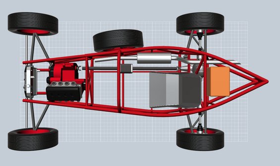
Image
high res: http://www.supermotors.net/getfile/1011085/original/ar6.jpg

the bottom tubes are well restrained with cross-tubing and (most likely) "welded in place" steel floor panels.
however, the upper radi is for large parts unrestrained ....
.... maybe i`m just "overthinking" this :ack:

vroom

the drawing is still largely unfinished ... especially the nose and rear are missing several braces
(the fuel tank will also get more surrounding protection)

yes, the tubing is probably grossly oversized (compared to other locosts) :o
i gave up on building a "super lightweight" BEC mainly for the reason that i want to be able to take this car off the road if i desire.

this is also the reason why i plan on conventional (exposed) coilover shocks;
so that i can adjust the coil preload (ride height) from the outside in a couple minutes.


btw
yes, that`s a spare tire in the drawing :mrgreen:

again, i borrowed the idea from the original :

Image

a must for extended off-road excursions but i`m thinking to add a "hitch tubing style" kinda thing,
so that i can remove the tire and its supporting structure for normal driving

_________________
- Stephan - Image


Top
 Profile  
Reply with quote  
PostPosted: February 11, 2014, 8:31 am 
Offline

Joined: August 12, 2012, 6:38 pm
Posts: 1937
Location: worcester county, Massachsetts
Rooster, looks slick! I would still not want the exhaust passing thru the cockpit (CO risk, farking lotsa heat, etc.) but the frame itself looks pretty kewl.

as far as bending the curves into the tubes, I would simply make a wooden form and then heat and bend the tubes around the form - similar to the method I've seen custom motorcycle builders create curved frame tubes.

I like your design enough, I may plagiarize it. maybe.

Oh as an aside, thqat Alfa P3 upthread has the alternatrive Dubonnet front suspension, replacing the usual double semi-eliptics. 1930's suspension weirdness - axle fixed hard to the front of the frame channels, with the spring and damper all inside the kingpins on each end.

_________________
The B-3 build log: http://www.locostusa.com/forums/viewtopic.php?f=36&t=13941 unfortunately, all the pictures were lost in the massive server crash

The beginnings of the Jag Special,
https://www.locostusa.com/forums/viewtopic.php?f=36&t=19012
Again, all pictures were lost.


Top
 Profile  
Reply with quote  
PostPosted: February 11, 2014, 4:46 pm 
Offline
User avatar

Joined: January 28, 2009, 2:10 pm
Posts: 20
Location: East Point, GA
Stephan, love what you're doing here. For your fuel tank, have you looked into something like these?

http://www.fuelsafe.com/store/sprint.html

Expensive, but close to the shape you need?

HTH,

John


Top
 Profile  
Reply with quote  
Display posts from previous:  Sort by  
Post new topic Reply to topic  [ 159 posts ]  Go to page Previous  1 ... 6, 7, 8, 9, 10, 11  Next

All times are UTC - 5 hours [ DST ]


Who is online

Users browsing this forum: No registered users and 12 guests


You cannot post new topics in this forum
You cannot reply to topics in this forum
You cannot edit your posts in this forum
You cannot delete your posts in this forum
You cannot post attachments in this forum

Jump to:  
POWERED_BY