LocostUSA.com

Learning how to build Lotus Seven replicas...together!
It is currently April 17, 2024, 9:57 pm

All times are UTC - 5 hours [ DST ]


Post new topic Reply to topic  [ 155 posts ]  Go to page Previous  1 ... 4, 5, 6, 7, 8, 9, 10, 11  Next
Author Message
PostPosted: February 17, 2019, 10:14 pm 
Offline
User avatar

Joined: May 29, 2015, 6:09 pm
Posts: 120
Location: Charlotte
TRX wrote:
Is that 1x2 tubing across the front of the cockpit?

They make push-in plastic plugs in 1x2" as well as 1x1".

https://www.amazon.com/Rect-Tubing-Plug ... B00ANN89LG

You have a good eye, yes that is 1 inch by 2 inch tubing.

Thanks for the tip


Top
 Profile  
Reply with quote  
PostPosted: February 17, 2019, 10:22 pm 
Offline
User avatar

Joined: May 29, 2015, 6:09 pm
Posts: 120
Location: Charlotte
Miatav8,MstrASE,A&P,F wrote:
I like this build also. Maybe you have special rules in your state for replicas that would make the atv bits a non-issue. Speaking of having episodes, I request, nay, demand to see this puppy in action! :shock: :cheers:

I can see the conflicts that led to the location of the fuel tank and filler. Here is another option that might appeal to you but the tank will have to be custom. Designed for a vented cap (air in and out versus just in). If the cap only allows air in, use a separate rollover valve, keep the standpipe on the filler neck, but omit the small hole.

Out of the line of sight, doesn't interfere with the pedals, maintains access to pedals, coilovers, and their reservoirs. Provides expansion space, reduces slosh, and keeps the outlet covered. I'm thinking .080" 6061 with 1/4" mounting ring and 3/8" block for the outlet for a pipe thread fitting. May want to rework the coilover mounts for clearance. You could make the tank wider at the top to overhang the subframe mounts and extend it forward for more capacity. Speaking of the mounts, you used hardened bolts but there is no positive stop except for the stiffness of the nylon sleeves that look pretty thin. A 1/4 wall uhmw sleeve would be a good compromise between a steel or aluminum inner sleeve and what you have now.

You could also put the radiator up front then use the space under the seat for storage like a glove box.

Seat could use upholstered squabs/cushions with velcro sewn to the back with adhesive back velcro on the metal, like airline seat bottom cushions.

An elbow in the flat base plate for the air filter mount would be easy to fab without compromising flow and will get the filter off the exhaust. Just pie wedges in the side view with a filler strip across the bottom. Cut the bottom and sides, then bend the center flap the air filter mounts to up for the desired clearance, cut paper patterns to fill the gaps. Happy to draw a picture if my words fail to convey. Also, the filter (cotton gauze) should be oiled just like the original.

Thanks for all the suggestions!

My next post will be all about the fuel system. Like your suggestions. It's a custom tank made of .080" aluminum.

After my fuel system post, the cooling system is next in line to be posted.

Stay tuned...


Top
 Profile  
Reply with quote  
PostPosted: February 19, 2019, 10:37 pm 
Offline
User avatar

Joined: May 29, 2015, 6:09 pm
Posts: 120
Location: Charlotte
Here is the video for all that went into my fuel system -> Click here

I started by mocking up a custom fuel tank using CAD (Cardboard Aided Design) :oops: Even a small 3 gallon tank can weigh 25-30lbs, so I designed the tank to fit under the seat to keep that weight low in the chassis. The tank is also centered in the chassis where it is most protected during a crash. The tank is shaped so it creates a smooth rising belly pan that leads fresh ram-air into the radiator, which is also mounted under the seat. The depth of the tank was set to be the same as the donor tank, so the fuel pump and fuel level sensor could be reused.
Attachment:
Tiger 700 16 Fuel System 20190118_Moment CAD.jpg

I don't have the equipment to weld Aluminum tanks, so I took the CAD tank to a local fabricator. It took a couple trips back to the fabricator to get it it right. The first attempt was 3/8" to big, so he had to cut off one end and weld it again. The second attempt had a pin hole leak, so a 20 second TIG zap plugged the hole. Fortunately, I leak tested the tank with water (vs fuel).
Attachment:
Tiger 700 16 Fuel System 20190118_Moment raw tank.jpg

The fuel filler comes out the left side and a polished flush mount aluminum cap will be installed in the side of the body. I had the fabricator weld an extra layer of aluminum inside the tank where the fuel sender is mounted. That ensured a solid flat surface for the sender gasket to seal upon. Since the sender mounting was different than the donor, I made a custom set of gaskets using a fuel safe Felpro 3157 gasket sheet.
Attachment:
Tiger 700 16 Fuel System 20190118_Moment gasket.jpg

The fuel injection line connectors are similar to those in a car. It takes a size E fuel injection connector release tool to remove the connector at the engine. The connector on the tank has a simple release clip that is pulled to disconnect it.
Attachment:
Tiger 700 16 Fuel System 20190118_Moment tank connected.jpg

Attachment:
Tiger 700 16 Fuel System 20190118_Moment filler.jpg

Attachment:
Tiger 700 16 Fuel System 20190118_Moment tank installed.jpg


The vent tube is routed up over the rear subframe down onto the other side. In a roll-over, that routing will keep the fuel in the tank.

Now the fuel tank, radiator, front suspension and most of the engine mass are mounted below the seat of my pants! Placing all the heavy components low in the chassis should translate into less body lean and less brake dive.

In fact, the driver sits higher than all those heavy components, so that makes me the most unstable part of the car :drive:


You do not have the required permissions to view the files attached to this post.


Top
 Profile  
Reply with quote  
PostPosted: February 20, 2019, 1:21 am 
Offline
Toyotaphobe
User avatar

Joined: April 5, 2008, 2:25 am
Posts: 4829
Location: Fort Worth, Texas
rumbles wrote:
In fact, the driver sits higher than all those heavy components, so that makes me the most unstable part of the car :drive:


JD I never knew Rumbles was your pseudonym?

_________________
mobilito ergo sum
I drive therefore I am

I can explain it to you,
but I can't understand it for you.


Top
 Profile  
Reply with quote  
PostPosted: February 20, 2019, 11:21 am 
Offline
We are Slotus!
User avatar

Joined: October 6, 2009, 9:29 am
Posts: 7651
Location: Tallahassee, FL (The Center of the Known Universe)
carguy123 wrote:
rumbles wrote:
In fact, the driver sits higher than all those heavy components, so that makes me the most unstable part of the car :drive:


JD I never knew Rumbles was your pseudonym?
I'm the most unstable part of any car or anything else I'm involved in. You should be scared... :evil:

_________________
JD, father of Quinn, Son of a... Build Log
Quinn the Slotus:Ford 302 Powered, Mallock-Inspired, Tube Frame, Hillclimb Special
"Gonzo and friends: Last night must have been quite a night. Camelot moments, mechanical marvels, Rustoleum launches, flying squirrels, fru-fru tea cuppers, V8 envy, Ensure catch cans -- and it wasn't even a full moon." -- SeattleTom


Top
 Profile  
Reply with quote  
PostPosted: February 28, 2019, 9:56 am 
Offline
Automotive Encyclopedia
User avatar

Joined: December 22, 2006, 2:05 pm
Posts: 8042
And now for something similar yet completely different. :cheers:


You do not have the required permissions to view the files attached to this post.

_________________
Miata UBJ: ES-2074R('70s maz pickup)
Ford IFS viewtopic.php?f=5&t=13225&p=134742
Simple Spring select viewtopic.php?f=5&t=11815
LxWxHt
360LA 442E: 134.5x46x15
Lotus7:115x39x7.25
Tiger Avon:114x40x13.3-12.6
Champion/Book:114x42x11
Gibbs/Haynes:122x42x14
VoDou:113x44x14
McSorley 442:122x46x14
Collins 241:127x46x12


Last edited by Miatav8,MstrASE,A&P,F on December 22, 2019, 6:45 am, edited 1 time in total.

Top
 Profile  
Reply with quote  
PostPosted: March 4, 2019, 10:05 am 
Offline
User avatar

Joined: May 29, 2015, 6:09 pm
Posts: 120
Location: Charlotte
Miatav8,MstrASE,A&P,F wrote:
And now for something similar yet completely different. :cheers:


Let's call it a "Go-Car"

Actually, my Tiger 700 has about the same amount of horsepower, but the engine is more lively with a RPM redline that is double that of a VW motor. Not to mention a 5 speed transmission vs 4 speed.

I measured the corner weights of my completed car (minus body and interior). It is 525lbs with 50/50 weight distribution. I'm guessing that the Go-Car in the photo weighs about twice that, with heavy rear distribution.

With body and interior, my Tiger 700 should be about 600lbs, which is less than many motorcycles. For example, a Honda VFR1200 is 589lbs and a Harley-Davidson Road Glide is 905 lb.

Put that all together and my Tiger 700 should be a spritely package with perky power and flickable handling.


Top
 Profile  
Reply with quote  
PostPosted: March 4, 2019, 12:55 pm 
Offline
Automotive Encyclopedia
User avatar

Joined: December 22, 2006, 2:05 pm
Posts: 8042
Apples to oranges of course but an interesting comparison.

Not exactly a fair comparison considering what can and has been done to a vw but the main thing is it can qualify for road use. Your curb weight, balance, number of gears, power, etc for the vw are not accurate either but this is not a race. Gocar is like a formula vee without the limitations/rules. Does it matter which one is better? Absolutely not.

Still waiting on that driving video. :cry:

_________________
Miata UBJ: ES-2074R('70s maz pickup)
Ford IFS viewtopic.php?f=5&t=13225&p=134742
Simple Spring select viewtopic.php?f=5&t=11815
LxWxHt
360LA 442E: 134.5x46x15
Lotus7:115x39x7.25
Tiger Avon:114x40x13.3-12.6
Champion/Book:114x42x11
Gibbs/Haynes:122x42x14
VoDou:113x44x14
McSorley 442:122x46x14
Collins 241:127x46x12


Top
 Profile  
Reply with quote  
PostPosted: March 4, 2019, 10:19 pm 
Offline
User avatar

Joined: March 30, 2011, 7:18 am
Posts: 1615
Location: central Arkansas
Where did that steering crush tube come from, if you know?


Top
 Profile  
Reply with quote  
PostPosted: March 5, 2019, 9:14 am 
Offline
Automotive Encyclopedia
User avatar

Joined: December 22, 2006, 2:05 pm
Posts: 8042
The collapsible section is two early bug steering shafts welded together. You can make your own by rolling 12ga flattened expanded metal into a tube, butt weld the sides and make heavy washers to the ends to attach thick wall 3/4 od dom. True the dom ends up by leaving them extra long to clamp into a jig for welding then cut to length.

_________________
Miata UBJ: ES-2074R('70s maz pickup)
Ford IFS viewtopic.php?f=5&t=13225&p=134742
Simple Spring select viewtopic.php?f=5&t=11815
LxWxHt
360LA 442E: 134.5x46x15
Lotus7:115x39x7.25
Tiger Avon:114x40x13.3-12.6
Champion/Book:114x42x11
Gibbs/Haynes:122x42x14
VoDou:113x44x14
McSorley 442:122x46x14
Collins 241:127x46x12


Top
 Profile  
Reply with quote  
PostPosted: March 6, 2019, 9:39 am 
Offline
User avatar

Joined: May 29, 2015, 6:09 pm
Posts: 120
Location: Charlotte
Miatav8,MstrASE,A&P,F wrote:
Apples to oranges of course but an interesting comparison.

Not exactly a fair comparison considering what can and has been done to a vw but the main thing is it can qualify for road use. Your curb weight, balance, number of gears, power, etc for the vw are not accurate either but this is not a race. Gocar is like a formula vee without the limitations/rules. Does it matter which one is better? Absolutely not.

Still waiting on that driving video. :cry:


Yup, it's not a competition, but it is a useful comparison. When I was in the design phase, I wanted to ensure that my small 700cc engine would be powerful enough to have good acceleration and handle freeway speeds. So I looked at other sub-100HP cars scenarios to ensure I wasn't building a slug.

The 2 key comparisons were:

  • The VW Beatle of the 1960s weighs 1700lbs (770kg) and had 40HP. The Beatle had adequate acceleration and could travel at highway speeds, but you had to push it.
  • The donor Raptor 700 ATV has 47HP and weighs 425lbs. It can reach speeds of 80MPH with exhilarating acceleration. This is done on low pressure knobby off-road tires with very high rolling resistance.

My Tiger 700 project has the same 47HP, but will weigh 600lbs. I targeted 600lbs because that is the donor's 425lbs plus a typical passenger weighing 175lbs. Since the Tiger 700 only has 1 driver seat, that ensures that the finished car is within the Raptor's original weight design parameters. I swapped the low pressure knobby tires for DOT 14" auto tires. The difference in rolling resistance is dramatically less. It took some muscles to just roll the Raptor around my garage on the knobbys. But on the DOT tires, I need to keep the Ebrake on to prevent it from rolling away on its own.

Bottom line: The Raptor engine combined with DOT tires, slightly higher gearing, and a more aerodynamic body should be able to handle freeway speeds with no problem. It won't have rocket like acceleration, but it should be "spunky" enough to be a lot fun


Top
 Profile  
Reply with quote  
PostPosted: March 6, 2019, 7:18 pm 
Offline
User avatar

Joined: May 29, 2015, 6:09 pm
Posts: 120
Location: Charlotte
Here's the video on the cooling system -> Click Here

I made the driver's seat a bit higher to allow the fuel tank and radiator to be mounted underneath. The fuel tank is shaped to help direct the ram air flow into the radiator. I used the donor's aluminum radiator and mounted it using the original rubber cushions, so the radiator should never stress crack.
Attachment:
Radiator under seat mount 2 small.jpg

The radiator is turned 90 degrees and mounted on its side with the inlet / outlet hoses at the bottom. That orientation made good packaging sense, but it causes a couple problems:
  • The cooling system generates steam and that air will be trapped at the top of the radiator. Eventually, there will be so much air trapped in the radiator that there will be no room for coolant. The solution is to vent the air out by adding a steam line at the top of the radiator and then plumb it to the highest part of the cooling system.
  • The radiator cap is now on the side and near the bottom of the cooling system. When the engine warms up, it will spill coolant first instead of air. Eventually, all of the coolant will be let out. The solution is to ensure there is another pressure relief valve at the top of the cooling system.
Attachment:
Radiator steamline and high pressure cap small.jpg

Enter expansion tank!
An expansion tank has several purposes. It sits at the highest point in the cooling system and allows air to gather there, so it can escape via its radiator cap. The expansion tank also helps separate steam from coolant to reduce cavitation. So...
  • The steam line from the radiator is connected to the expansion tank.
  • The radiator cap on expansion tank is rated at a much lower blow-off pressure that the cap that's on the radiator. When the engine warns up, steam will escape from the lower pressure cap at the top.

I used CAD (Cardboard Aided Design) to design the expansion tank. I located the hose inlets so it would improve the hose routing to the other cooling system components. Fabricating aluminum tanks is above my pay grade, so I had a local fabricator build it for me.
Attachment:
Expansion tank mockup done small.jpg

Attachment:
Expansion tank mockup done bottom small.jpg

When I had the cooling system all together, I wanted to ensure the radiator was filling to the top. So I held my hand at the top of the radiator to ensure it felt as hot as the bottom...Success!

Note: The video doesn't show the radiator overflow drain line. Its is now connected to the Raptor's coolant recovery tank.


You do not have the required permissions to view the files attached to this post.


Top
 Profile  
Reply with quote  
PostPosted: March 21, 2019, 5:54 pm 
Offline
User avatar

Joined: May 29, 2015, 6:09 pm
Posts: 120
Location: Charlotte
All the driver controls are now complete.

Here is the video on the driver controls -> Click here

Steering
It was a twisted tale to connect the rack & pinion unit to the steering wheel. The steering shaft on the Mustang II rack & pinion unit is on the far right and it points in the wrong direction (outward). So the challenge was to get the steering shaft heading back toward the driver with 2 universal joints. Even with 2 universal joints, each joint had to accommodate about a 35 degree the angle. That's right at the maximum angle for a single knuckle joint, so I went to double knuckle joints to ensure smooth rotation. I welded in 2 hiem bearing rod ends to securely hold the shafts and joints in place.

I then fabricated the steering column by welding flush mount hiem bearings on each end of 2" steel tube. I topped it off with a quick disconnect steering wheel to ensure easy access to the cockpit.
Attachment:
Steering column and ujoints.JPG


Shifter
The donor had a motorcycle like 5 speed sequential transmission with reverse. I fabricated a simple remote shift lever and connected a 30" automotive automatic shift cable via clevis pin. Then I cut the foot shift lever on the transmission and replaced it with a bracket to connect the the other end of the shift cable. The reverse gear is one shift down from 1st gear (R1N2345) and there is a mechanical lock out to ensure you don't go into reverse by accident. The lockout knob is cable operated and fortunately the cable was long enough so I could mount it just ahead of the seat as is.
Attachment:
Shifter mount.JPG
Attachment:
Shifter mount 2.JPG
Attachment:
Shifter mount 3.JPG

Parking Brake
The donor also came with a parking brake. Like the reverse lockout knob, the cable was long enough so I could mount it just ahead of the seat as is.
Attachment:
ebrake mount.JPG

Brakes
The donor had a brake on each front hub and only one in rear since its a live axle with no differential. Fortunately, the brake calipers use automotive style brake banjo bolts, so parts were easy to find. I replaced the hand/foot controls with a Wilwood pedal assembly that is mounted solid to the chassis. I'm trying to leave as much room as possible for a trunk in the front, so I choose a pedal assembly with the master cylinders are mounted facing rearward. I started with dual 5/8" bore master cylinders, but they didn't have enough line pressure to lock up the brakes. I down sized both master cylinders to 1/2" bore and now I have plenty of stopping power. Its almost like power brakes. I added a Wilwood proportioning valve to help balance the front to rear braking power.
Attachment:
Brake pedal assy.JPG

Clutch
The donor had a cable operated clutch. I found an extra long universal motorcycle cable that would reach the pedal assembly and fabricated a bracket for it. I then tried several different settings at the pedal to match full pedal depression with proper clutch cable movement. The end result was a very light pedal, but with good clutch control.
Attachment:
clutch cable.JPG
Attachment:
clutch stop.JPG

When the clutch pedal was released, it would flop loosely since there was no positive stop on the pedal assembly. I fabricated an internal spring loaded stop to solve the problem.

Throttle
The donor had a cable operated throttle as well. Like the clutch, I found an extra long universal motorcycle cable that would reach the pedal assembly and fabricated a bracket for it. I found a hot rod style accelerator pedal that somewhat matches the Willwood pedals. The throttle also took several attempts to find a good match between full pedal depression and full throttle. The end result was good engine control.
Attachment:
Throttle pedal.JPG


You do not have the required permissions to view the files attached to this post.


Top
 Profile  
Reply with quote  
PostPosted: March 21, 2019, 7:17 pm 
Offline
Automotive Encyclopedia
User avatar

Joined: December 22, 2006, 2:05 pm
Posts: 8042
Nice update. I like the clutch pedal stop/return. I mounted my rad sideways too, on the diesel reverse trike.
If you route the throttle cable from below and make a tab that bolts onto the existing pedal and wraps around to the side of the frame tube, the abrasion on the cable where it enters the sleeve can be reduced. However, it may last long enough as-is that you never have a cable failure.

_________________
Miata UBJ: ES-2074R('70s maz pickup)
Ford IFS viewtopic.php?f=5&t=13225&p=134742
Simple Spring select viewtopic.php?f=5&t=11815
LxWxHt
360LA 442E: 134.5x46x15
Lotus7:115x39x7.25
Tiger Avon:114x40x13.3-12.6
Champion/Book:114x42x11
Gibbs/Haynes:122x42x14
VoDou:113x44x14
McSorley 442:122x46x14
Collins 241:127x46x12


Top
 Profile  
Reply with quote  
PostPosted: June 19, 2019, 3:05 pm 
Offline
User avatar

Joined: May 29, 2015, 6:09 pm
Posts: 120
Location: Charlotte
I have completed the electrical system. All the electrical components are mounted and everything works.

Here's a link for the video on Youtube -> https://youtu.be/4YYH08fFflQ
Attachment:
electrical overview small.jpg

Electrical Harness
There really are no electrical harnesses available from Painless, American Wire, or other suppliers to fit my application. So I had to modify many portions of the existing electrical system, as well as design other areas like the turn signals. I wanted the Tiger 700 easy to work on, so I labeled all the connectors and ran all of them to the left side of the chassis. That way, all the plugs are together and its simple to troubleshoot any gremlins that rear their ugly head. The plugs are also located where the rear sub-frame bolts to the center chassis. If I ever need to separate the center chassis from the rear sub-frame, I can simply disconnect the plugs to separate the front harness from the rear portion.
Attachment:
Electrical harness on right side small.jpg

Gauge Cluster
The gauge cluster starts with the original Raptor 700 warning lights. The harness to the warning lights just needed to be extended to reach the dashboard ahead of the driver. My cable stretcher tool came in very handy :leave:

I then mounted a TrailTech Vapor digital gauge cluster that includes a speedometer, odometer, tachometer, and coolant temperature. I also mounted the TrailTech Vapor's optional surround bezel that houses 4 more warning lights. I wired the lights to indicate left signal, right signal, hi/lo beam, and left one for a spare. The gauge cluster is on a temporary steering column mount for now. I plan to eventually mount it in the fiberglass bodywork.
Attachment:
Gauge cluster small.jpg

Ignition
The process of starting the Yamaha Raptor 700 required many steps.
  • Turn the overall power key switch on
  • Turn the engine switch on
  • Turn off the kill switch
  • Press the brake.
  • Press the start button

One of the themes of the Tiger 700 is to make it simple and fun to drive. So I wanted to simplify the way you start the engine and use a familiar automotive key ignition switch. This took numerous modifications to the existing ignition circuit as well as adding a relay circuit to make it all work with a twist of a key.

Headlights and Running
Like the ignition, I wanted to simplify operating the lights as well. I modified the lighting circuit to replace all the switches with a familiar automotive push/pull light switch.
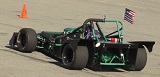
Steering Column Controls
The Tiger 700 doesn't have doors. Instead, it has a step on the right side of the body to help the driver climb into the cockpit from the top. The steering wheel may make it difficult to enter or exit the cockpit, so I installed a steering wheel quick disconnect. I also predicted that a traditional turn signal stalk could be broken during driver entry/exit, so I decided to place those controls on the steering wheel, along with the horn and a hi/low beam switch. To keep the entry/exit simple, I decided to make all the switches wireless on the quick disconnect steering wheel. I found a wireless system with 4 receiver channels and a key fob style control. I disassembled the key fob and soldered wires onto the 4 internal switches and ran them to the steering wheel controls. The whole system is tucked neatly into the back side of the steering wheel you never see. The 4 receiver channels have hard coded frequencies and switch functions. For example,
  • The horn button channel uses a momentary switch. In other words the switch closes momentarily when the horn button is pressed, and opens with the horn button is released.
  • The other 3 button channels use a toggle style switch. The switch toggles closed when the button is pressed and it stays closed when the button is released. The switch toggles back open when the button is pressed a second time. This type of switch works well for the turn signals and hi/lo beam.
Attachment:
Remote 2 small.jpg
Attachment:
Steering wheel remote 3 small.jpg

Reducing Power Consumption
The alternator on the donor Raptor 700 only produces about 20 amps. About 15 of those amps were devoted to the lights. To reduce the power consumption, I converted all the lights to LED, even the headlights. With all the indicators, running lights, brake lights, and both hi/lo beams on, the current only measured 4.5 amps! This ensures I have plenty of extra power for a possible audio system and a larger radiator cooling fan.

At the end of the video, I cover the pros and cons of soldering vs crimping wire connections.

There was quite a bit of information on the electrical system, so I will split it into 2 episodes. The next episode will cover the circuit design in more detail.

Oh joy, you have more electrical gremlins to look forward to :drool:


You do not have the required permissions to view the files attached to this post.


Top
 Profile  
Reply with quote  
Display posts from previous:  Sort by  
Post new topic Reply to topic  [ 155 posts ]  Go to page Previous  1 ... 4, 5, 6, 7, 8, 9, 10, 11  Next

All times are UTC - 5 hours [ DST ]


Who is online

Users browsing this forum: No registered users and 31 guests


You cannot post new topics in this forum
You cannot reply to topics in this forum
You cannot edit your posts in this forum
You cannot delete your posts in this forum
You cannot post attachments in this forum

Jump to:  
POWERED_BY