Hermit wrote:
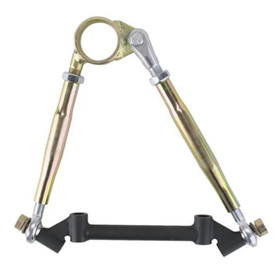
Is there any reason you couldnt have the connections on the ball joint end both pivoting like it is on the right, instead of the left solid and right pivoting.
While you might be able to design a symmetric solution, having 3 joints on that end would under constrain the upper ball joint and let the spindle flop around like a wet noodle. There are other versions that bring the clevis mount around so that both links would come in at more of the same angle, although it will reduce coilover space somewhat.
Kartracer47 wrote:
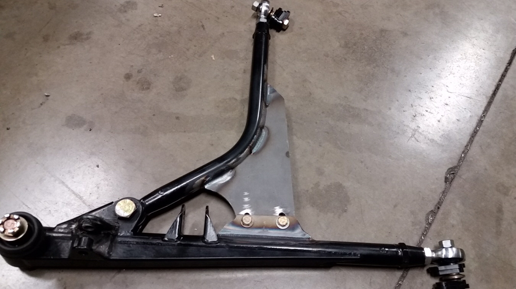
The control arms that are shown in the first post are DOUBLE adjustable on close inspection. The rod ends are threaded into a threaded bushing(right/left threads). This allow for camber and caster adjustments without removing the chassis attach bolts.
The rod end positions may be adjustable, but any adjustment you make to just one of them will change the distance between the rod ends. The distance between the chassis mounts in this configuration is generally fixed. Without flexing the mounting brackets, there is a (limited) singular arc of combined caster/camber adjustment that can be made while maintaining the distance between the rod end centers. As noted, because of their position/angle relative to each other, it's almost all camber with very little caster change. Which is good, because more camber actually necessitates less caster in this configuration. However, there also appear to be unequal length spacers on either side of the rod end as well, potentially allowing a second option for distance between mounts. This would provide a binary adjustment shifted primarily for caster. Assuming the rear mount axis is correct as shown, which it often is, the unequal spacers would give small binary adjustment in anti-dive.